Navigation
Temperature compensation
NOTE: Thermal compensation is activated and setup through UCCassist-2.
Axis sensors
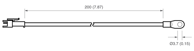
Axis sensors are required to monitor and compensate for any temperature changes within the CMM's scale. The axis sensor is housed in a potted ring terminal with a Ø3.7 mm hole which can be screwed or glued in position using a thermally conductive glue. The axis sensors are supplied with a 200 mm cable (attached) with a male JST connector fitted to the end. The mating part of the connector is supplied as part of the axis sensor kit.
Workpiece sensors
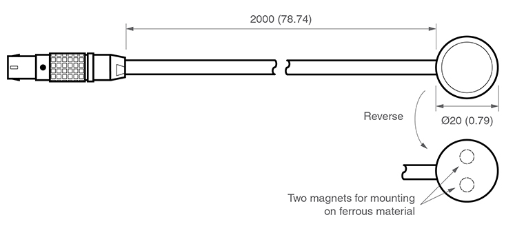
Workpiece sensors are required to monitor and compensate for any temperature changes of the workpiece material. They can be magnetically mounted or clamped to the workpiece. The sensors are housed in a Ø20 mm aluminium body with a polyacetal sleeve. The sensors should always be handled by the polyacetal sleeve in order to reduce any thermal effects. The sensors are supplied with a cable length of 2000 mm and have a LEMO connector fitted. The mating part of the connector is supplied as part of the workpiece sensor kit in in-line form.
Pin allocation
With the red dot on the LEMO pointing upwards:
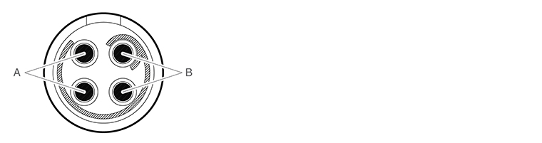
- ‘Pair A' - Top left pin and bottom left pin
- ‘Pair B' - Top right and bottom right
NOTE: Ensure the sensor is connected to the controller with one pin from ‘pair A' and one pin from ‘pair B'.
Workpiece sensor
Ensure the workpiece sensor is in full contact with the workpiece.
Aim to position the workpiece sensor in the middle of the workpiece or near where the measurement is taking place.
Electrically ground workpiece prior to using the thermal effect compensation system to avoid electrostatic discharge (ESD) through the workpiece sensor.
Use multiple sensors for large workpieces.
Handle the workpiece sensor by the white sleeve if possible or wait for five minutes once the sensor is in position before proceeding to take a measurement.
Keep the workpiece sensor cabling away from moving sections of the CMM.
NOTE: It is not recommended to run axis thermal compensation without workpiece compensation (where axes and workpiece are at the same temperature) as it is unlikely that reliable results will be obtained.
Axis sensors
Ensure the sensors are mounted as close as possible to the axis scales
It is recommended to have at least two sensors per axis to account for temperature gradient effects
On large or high specification CMMs, use more than three sensors per axis
Thermally conductive glue should be used when gluing axis sensors to an axis
All axis sensor cabling must be tightly secured to the axis body to prevent it getting trapped during moves
Sensor resistance checks
A resistance check test is recommended:
- During system installation once all sensor cabling has been completed
- After every hardware change to the system (e.g. sensor, cable or switch change)
- Every six months, after the system has been commissioned, to check for any sensor failure or cabling issues
Resistance check procedure
- Regulate the temperature of the CMM room to a constant temperature between 16 °C and 28 °C.
- Allow the CMM to stabilise thermally for a minimum of one hour.
- Measure the sensor resistance from the CMM controller connector. This will ensure all intermediate cable and connections are correct.
- All workpiece and axis sensor resistance measurements should be within this range; 8.4 kΩ < R < 15.7 kΩ.
Best practise for using the thermal compensation system
- Ensure the CMM is not subjected to unnecessary changes in temperature (fans blowing, close to radiator, in direct sunlight or any other powerful radiant sources)
- Excessive humidity should be avoided
- Use the system as close as possible to the calibrated temperature
- Renishaw recommends that workpiece and axis sensors are verified at six month intervals
System accuracy and calibration
The TEC system can be used without calibration. The system accuracy is ±0.2 °C.