Navigation
Connecting the UCC controller - UCC T5
Hardware connection
The host PC must have a dedicated ethernet connection to the UCC controller. It is recommended that this is NOT a USB plug-in adapter because of the reduction in speed of operation these devices normally produce.
If the host PC is also to be connected to a network, it is necessary to install additional hardware within the host PC to permit a dedicated connection to be available for UCC controller communication. For details on how to install additional hardware into the host PC, please refer to the PC's installation / users guide.
The UCC controller is capable of using 10 Mbps, 100 Mbps and 1 Gbps ethernet. The selection is determined by the capability of the network adapter to which it is connected. It is recommended that a 100 Mbps network adaptor is used.
A 5 m CAT 5E cross-over ethernet cable is provided for this link as part of the UCC controller kit. Other lengths may be used, but the maximum is governed by the generic specification for ethernet connections (i.e. a hundred metres) which is sufficient for any CMM installation.
If there are concerns about EMC disruption due to the environment, or the routing of the cable, then the using a shielded cable is recommended.
It is suggested that the cross-over cable is labelled as a cross-over cable looks identical to a normal ethernet cable.
Software installation
The UCCassist-2 software must be installed on the host PC prior to connection of the UCC controller.
The latest version of UCCsuite can be downloaded from the Renishaw website for anyone with a MyRenishaw account. UCCsuite will install UCCassist-2 and UCCserver to enable the hardware set-up.
After the software has been installed, one of the utility sequences available is “IP Configurer” which is used to give the UCC controller an IP address and establishes the pairing of the PC and the UCC controller.
Configuration of IP addresses
This section describes the steps needed to connect the UCC controller to the host PC and configure the ethernet communication link.
NOTE: The examples used in this section are for Windows10 Professional and will vary for other operating systems.
IP addressing
Choose an IP address for the UCC controller and an IP address for the PC's network adaptor that are of the same class:
| class A 1.0.0.1 – 126.255.255.254 | For class A networks, a network is defined by the first number. |
| class B 128.0.0.1 – 191.255.255.254 | For class B networks, a network is defined by the first two numbers. |
| class C 192.0.0.1 – 223.255.255.254 | For class C networks, a network is defined by the first three numbers. |
NOTE: The last number must not be 0 or 255.
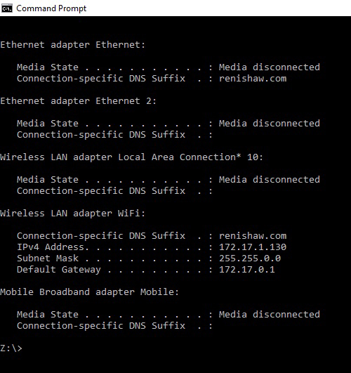
If there is more than one network connection in the PC, choose a network class for the UCC - PC connection that is not currently in use to keep the connections clearly separate. To find out which IP address the other network interfaces use, bring up the command prompt, then type “ipconfig”. Its output will look similar to this:
Setting the IP address of the PC
The process to set the IP address on the PC varies with each version of Windows. Administrator rights are needed in order to perform this operation.
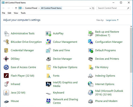
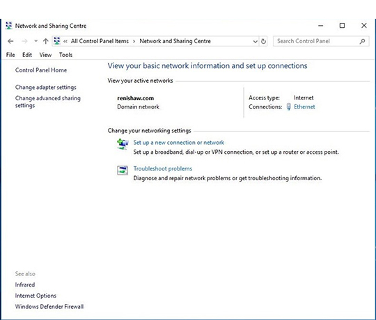
a) Navigate to 'Control Panel', then select 'Network and sharing centre':
b) Select 'Ethernet' in 'Access type connections':
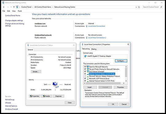
c) Click on 'Properties' and select ‘Internet Protocol (TCP/IPv4)' and click 'Properties'.
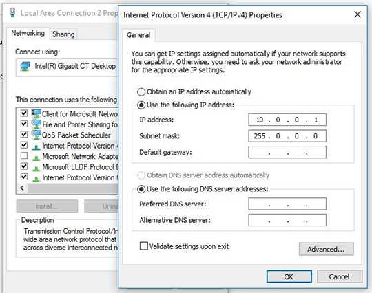
d) Select ‘Use the following IP address' and type in the IP address to use for the PC end of the comms link. Click in the Subnet mask field. On Windows10 the Subnet mask will already be filled in. If you have to fill it in for yourself, here are the values:
Class of network IP address belongs to | Subnet mask to use |
A | 255.0.0.0 |
B | 255.255.0.0 |
C | 255.255.255.0 |
Leave the 'Default gateway' field blank.
Example:
e) Click 'OK' and then 'OK' again. On earlier versions of Windows the PC needs to be rebooted.
Setting the IP address of the UCC controller
The UCC controller is not intended to be used on a corporate network. It is extremely important that the setting of the IP address of the UCC controller is on a dedicated connection. It is also important that the connection is not “firewalled” at the PC end. Administrator rights are needed in order to perform this operation.
Turn on the UCC controller and press the reset button (within 15 seconds), then wait for it to boot up.
It will enter its IP configuration state, shown by the 'Error' LED flashing rapidly.
Now start UCCassist-2 and the UCC IP configuration utility or commissioning sequence on the PC.
a) Login to UCCassist-2 → Go to 'Utilities bar' → Select 'IP Configure':
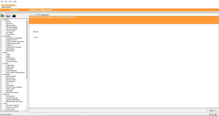
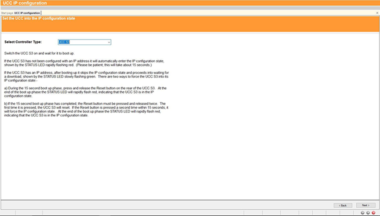
b) Pressing 'Next' will bring up a screen to allow the specific controller to be selected. It will also give instructions on getting the controller into IP configure mode depending on if it has already been configured or has no current configuration.
c) Click on the drop-down icon and select the IP address of the network adapter into which the UCC controller is plugged (this should be the one on which the IP address was set in 'Setting the IP address of the PC').
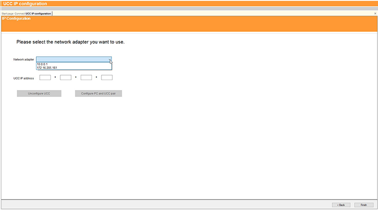
d) The UCC controller does not have an IP address. Type in the relevant address to match the network adapter in the PC. In the case below this is 10.0.0.1:
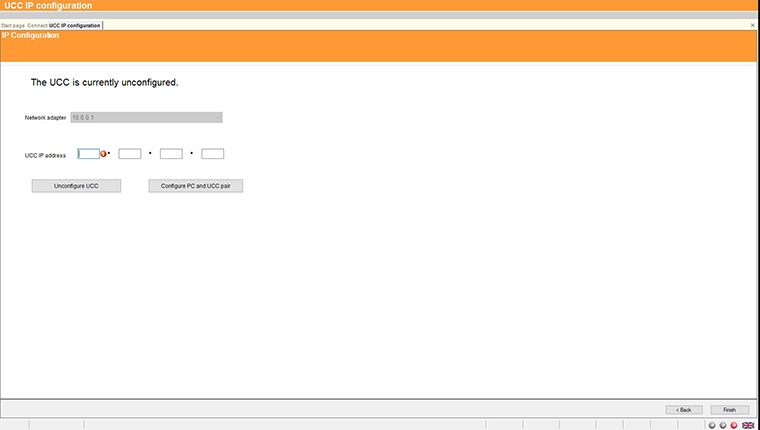
e) Fill in the desired IP address. The IP configuration software has given you a head start by filling in the network part of the address appropriate for the network adapter selected (see section 'IP addressing' for a discussion of the choice and of IP addresses in general).
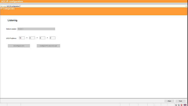
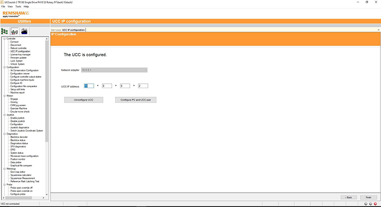
f) Click on ‘Configure PC and UCC pair'. If all is well this will result in the address being applied to the controller and the IP configure screen will close. If the controller is already configured a dialogue box saying the UCC is configured will open. Click 'Next' to finish.
Changing the IP address of the UCC
If the UCC controller already has an IP address, after booting up it skips its IP configuration state and proceeds into waiting for a download, shown by the status LED flashing slowly. There are two ways to force the UCC controller into its IP configuration state:
a) During the 15 second power up phase, before the error LED comes on, press and release the 'Reset' button on the rear of the UCC controller. At the end of the power up phase the error LED will flash rapidly indicating it is in the IP configuration state.
b) If the UCC controller has already powered up with the error light flashing slowly, i.e. about once per second, or even if the control software has been downloaded, the reset switch will need to be pressed twice. The first time to reset the controller then a second time, within 15 seconds, to force the IP configuration state.
The UCC controller is now in its IP configuration state, and the UCCassist-2 IP configuration software can be run on the PC, selecting the appropriate network adapter required. The current IP address of the UCC controller will be displayed. Type in the new one and click on ‘Configure PC and UCC pair'.
Establishing a new UCC - PC pairing
If a different UCC controller is connected to the PC, or a different PC to the UCC controller or even if the network settings on the PC are modified, ensure that they are a matched pair. To do this, go through the procedure in the 'Setting the IP address of the PC' section, even if you do not wish to change the IP address of the UCC controller (if the IP address is already suitable, then you do not need to re-type it). Clicking on ‘Configure PC and UCC pair' will establish the new pairing.
Downloading
The name of the downloadable file is specific to the controller so the correct controller needs to be selected to select the correct downloadable. Other controller downloadables will not work on a different controller. Remember to change the name in any configuration settings appropriate for the front-end.
The UCC controller system should now be established.