Navigation
The MCR20 module change rack
The MCR20 probe module changing rack kit comprises the following primary components:
- One Renishaw MCR20 probe module changing rack
- One Renishaw SCR200 mounting kit
- One location piece
- One Renishaw PS2R stylus
- Two Renishaw TP20 probe modules (probe module combination supplied will depend on part number of kit)
The MCR20 probe module changing rack, which can be easily mounted onto a CMM using the Renishaw SCR200 mounting kit and location piece, is designed to securely hold stored probe modules for automatic changing, and to protect these stored probe modules from airborne contaminants that may be present within the working environment. Only seven datum points are needed to set the MCR20 rack alignment and probe module changing co-ordinates.
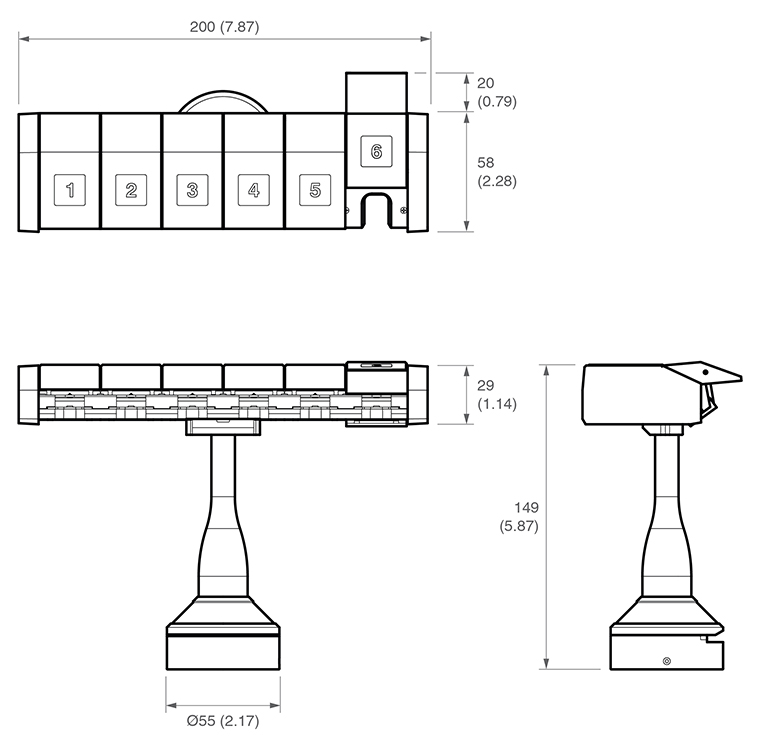
NOTE: Dimensions in mm (in).
When using the rack, the inhibit version of the TP20 probe must be used. By generating a magnetic field about the front of each docking port lid, the MCR20 effectively 'closes' the probe's inhibit switch during a probe module changing cycle. Rack function is completely passive and no electrical input is required.
During automatic changing of probe modules, limited crash protection is provided by hinged overtravel mechanisms incorporated within both the base and the docking port assembly of the MCR20. Provided any collision occurs in the direction of overtravel, the hinged overtravel mechanisms can be manually reset and normally it should not be necessary to re-datum the rack.
MCR20 probe module changing rack kits are available with the following combinations of probe modules and may be ordered from your supplier:
MCR20 probe kit number | LF | SF | MF | EF | Part number |
|---|---|---|---|---|---|
1 | 2 | A-1371-0261 | |||
2 | 1 | 1 | A-1371-0262 | ||
3 | 1 | 1 | A-1371-0263 | ||
4 | 2 | A-1371-0264 | |||
5 | 1 | 1 | A-1371-0265 | ||
6 | 2 | A-1371-0266 | |||
7 | 1 | 1 | A-1371-0267 | ||
8 | 1 | 1 | A-1371-0268 |
Mounting the MCR20 onto the CMM
To mount the MCR20 probe module change rack onto your CMM, carry out the following procedure:
1. Place the location piece in the desired position on the CMM table and secure in place using the M8 / M10 bolt and washer supplied. Using the appropriate Allen key (supplied), fully hand-tighten the M8 / M10 bolt into the threaded insert within the CMM table.
The MCR20 is not designed for horizontal operation with the ports in a vertical orientation.
2. Mount the lower base of the MCR20 probe module change rack over the location piece and rotate the X-axis of the rack until the required alignment is obtained.
3. Using the 1.5 mm hexagonal key supplied, fully hand-tighten the M3 cone point grubscrew (0.5 Nm to 1 Nm) to lock the MCR20 in position.
WARNINGS: The use of eye protection is recommended.
Pinch hazards exist between parts and between moving and static parts. Beware of unexpected movement. You should remain outside the full working envelope of probe head / extension bar / probe combinations.
It is the machine supplier's responsibility to ensure that the user is made aware of any hazards involved in operation, including those mentioned in Renishaw product documentation, and to ensure that adequate guards and safety interlocks are provided.
Under certain circumstances, the probe signal may falsely indicate a probe seated condition. Do not rely on probe signals to stop the machine.
It is strongly recommended that the EM1 STD and EM2 STD probe extension modules are not used for datuming of the MCR20, as the extended probe length may lead to increased concentricity errors within the probe system.
The following instructions assume that uncompensated probing points are taken, and therefore that the target positions for port docking are absolute machine co-ordinates.
Dimensions: | |
|---|---|
Length | 200 mm |
Width | 60 mm |
Height | 145 mm |
Port entry velocity | Maximum 800 mm/s |
Mounting orientation | Not designed for horizontal operation with the ports in a vertical orientation |
Y-axis overtravel | Hinged breakout from base 55 mm travel at port height |
Z-axis overtravel | Hinged docking port assembly 90° travel in –Z axis |
Inhibit range | 100 mm from port centre |