Navigation
Establishing a docking position for SH25 stylus holders
This section describes how to establish the docking position for the SH25 stylus holder. The docking position is defined by taking a series of measurements using the stylus holder setting piece (SHSP). The SHSP is a dummy stylus holder with a short cylindrical stem of a qualified length and diameter. This provides known constant values to accurately calculate the port docking position.
Eye protection should be work during this procedure and a good level of lighting is recommended to ensure no collisions occur.
It is necessary to turn off tip radius compensation when taking points using the SHSP because it is not calibrated. However, a suitable tip qualification (calibration) should be applied as detailed below.
Before taking points using the SHSP, a probe tip qualification should be applied that has previously been defined for a suitable configuration of SM25 scanning modules, SH25 stylus holder and stylus length. This configuration should be the shortest length possible, for example SM25-1, SH25-1 and a 21 mm stylus. In instances where SM25-3, SH25-3 and a 21 mm stylus is the only configuration available, it is recommended that the approach speed when taking points is restricted to 3 mm/s or less.
If using a threshold deflection method to measure points, the threshold deflection should be set to 0.050 mm.
CAUTION: Failure to follow the above recommendations could lead to severe damage of the SM25 scanning module when taking points with the SHSP.
1. Latch the port lids open using the triangular plastic inserts provided
2. The desired port should be fitted with a PA25-SH port adapter insert. Orientate the PA25-SH as shown in the image below. Slide the port adapter into the port ensuring that the side lugs of the adapter locate in the slots at either side of the port. Push the PA25-SH port adapter in to the port until it clips securely in to the port. Check that the adapter is fitted correctly and that there is no misalignment.
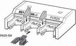
Steps 1 and 2 - latching port lids open and placing PA25-SH into desired port(n)
3. Ensure the probe head is orientated at an A0 B0 position.
4. Inhibit the probe signal through software.
5. Mount the desired SM25 scanning module to the SP25M probe body.
6. Mount the SHSP to the probe module as described above.

Step 6 - the SHSP is mounted to the SM25 scanning module
7. Enable the probe signal through software (probe signal now armed).
8. Turn off tip radius compensation.
9. Measure a point on the top of the port [P1], offset the point by -20 mm in the Z-axis.
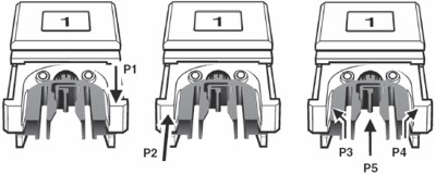
Step 9 - take a point on port top surface
Step 10 - take a point on port front side face
Step 11 - taking 2 points on port inside rails
10. Measure a point on the front lip of the port [P2], offset the point by + 16 mm in the Y-axis.
11. Measure two points [P3 and P4] on the inside rails of the port and construct a point [P5] between them.
12. Create a datum coordinate system for the stylus holder docking position of the port. This will be at the X position of P5, the Y position of P2 and the Z position of P1 – [dat_SH_port(n)].