Navigation
Head alignment for ACR3
It is necessary for the probe head to be aligned with both the movements of the CMM and the ACR3. This is because the autojoint is a high force mechanical joint that could cause operational errors if used with an incorrectly aligned ACR3.
NOTE: The Renishaw PH10 PLUS motorised head system has been designed so that the roll and pitch of the autojoint is held within the tolerances required for the ACR3 system, when connected to a standard Renishaw shank.
In the majority of installations only the yaw of the motorised head requires alignment. However, it is possible that the location of the probe head shank to the CMM quill, or the mounting face of the PH10MQ PLUS to the CMM quill, is not held to the required tolerances. In some cases, this could result in excessive ACR3 port wear or failure of the ACR3 to change probes.
This problem can be rectified by using either the AM1 or AM2 adjustment module.
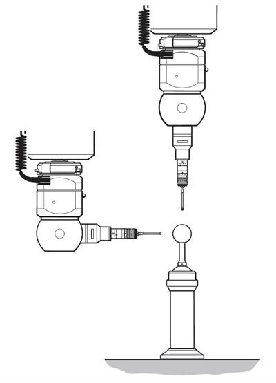
Alignment of the head - roll
The roll axis of the head is from the left-hand side to the right-hand side of the probe head. The maximum recommended alignment error is 0.2°.
The recommended procedure for setting the roll of a motorised or indexing probe head is as follows:
NOTE: During this procedure the probe should not be qualified.
1. Index the probe head to an A-axis position of 90° and a B-axis position of -90°.
2. Using the probe attached to the probe head, measure the qualification sphere on the CMM table (sphere 1). Use the centre of this measured sphere as a datum.
3. Index the probe head to an A-axis position of 90° and a B-axis position of 90°.
4. Using the probe attached to the probe head, measure the qualification sphere on the CMM table (sphere 2).
5. Calculate the roll angle for the probe head using the following formula:
arc TAN {Z axis position of sphere 2 / Y axis position of sphere 2} = Roll angle (recommended <0.2°)
6. If the roll angle exceeds 0.2° then adjustment is required, please refer to ‘Adjusting the AM1' or ‘Adjusting the AM2' as appropriate and repeat steps 1 to 5.
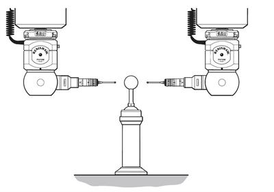
Alignment of the head - pitch
The pitch axis of the head is from the front of the probe head (where the LED is located) to the rear of the probe head. The maximum recommended alignment error is 0.2°.
The recommended procedure for setting the pitch of a motorised or indexing probe head is as follows:
NOTE: During this procedure the probe should not be qualified.
1. Index the probe head to an A-axis position of 90° and a B-axis position of 0°.
2. Using the probe attached to the probe head, measure the qualification sphere on the CMM table (sphere 1). Use the centre of this measured sphere as a datum.
3. Index the probe head to an A-axis position of 90° and a B-axis position of 180°.
4. Using the probe attached to the probe head, measure the qualification sphere on the CMM table (sphere 2).
5. Calculate the pitch angle for the probe head using the following formula:
arc TAN { Z axis position of sphere 2 / X axis position of sphere 2 } = Pitch angle (recommended <0.2°)
6. If the pitch angle exceeds 0.2° then adjustment is required, please refer to ‘Adjusting the AM1' or ‘Adjusting the AM2' as appropriate and repeat steps 1 to 5.
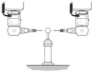
Alignment of the head - yaw
The yaw axis of the head is the rotational axis of the probe head with respect to the quill of the CMM. The maximum recommended alignment error is 0.2°.
The recommended procedure for setting the yaw of a motorised or indexing head is as follows:
NOTE: During the procedure the probe should not be qualified.
1. Index the probe head to an A-axis position of 0° and a B-axis position required for an autojoint probe to enter the ACR3.
2. Using the probe attached to the probe head, measure the qualification sphere on the CMM table (sphere 1). Use the centre of the measured sphere as a datum.
3. Index the probe head to an A-axis position of 90°, maintaining the same B-axis position as in step 1.
4. Using the probe attached to the probe head, measure the qualification sphere on the CMM table (sphere 2).
5. Calculate the yaw angle of the probe head using the following formula:
arc TAN { X axis position of sphere 2 / Y axis position of sphere 2 } = Yaw angle (recommended <0.2°)
6. If the yaw angle exceeds 0.2° then adjustment is required, please refer to ‘Adjusting the AM1' or ‘Adjusting the AM2' as appropriate and repeat steps 1 to 5.