Navigation
UCC T3 PLUS and UCC S3 installation and connection details
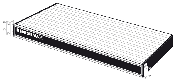
Dimensions

NOTE: Dimensions in mm (in).
Weight | 2.1 kg (4 lb 10 oz) |
UCC T3 PLUS or UCC S3 can either be free-standing or used in a 19 inch rack system.
WARNING: Ensure the UCC T3 PLUS / UCC S3 is disconnected from the mains supply during installation.
Free-standing installation
The UCC T3 PLUS / UCC S3 unit draws air from the right hand side when viewed from the front and expels air out of the left hand side. A minimum clearance gap of 10 mm is necessary between the sides of the unit and any potential obstruction.

Mounting in a 19 inch rack
The rack mounting kit (part number A-5518-0005) contains two brackets and four M5 × 6 mm screws.
Assemble the brackets to the UCC T3 PLUS / UCC S3 as shown below:
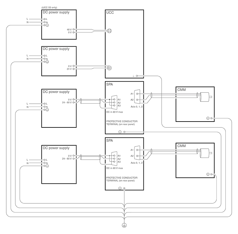
Earth bonding scheme
PH10 head connector (15-way 'D' type socket)

NOTE: For maximum immunity from electrical noise, Renishaw recommends that:
- Mating shells connectors must be metal bodied.
- The overall cable screen is continuous and connected to the system ground on the user's equipment through the bodies of the connectors.
CAUTION: For correct system function, the maximum overall single core resistance between the head and the controller MUST be less than 2.5 ohm.
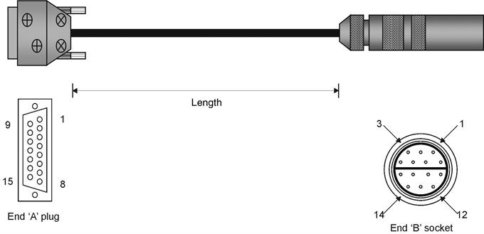
Machine cable:
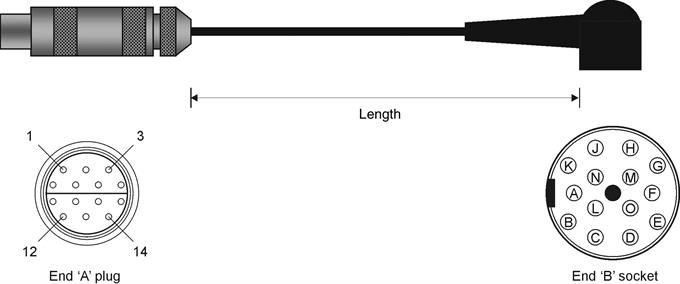
Probe head cable:
Controller | Controller | Head | Head | Maximum | ||
|---|---|---|---|---|---|---|
Signal name | 15-way male 'D' type | Cable PLM 6 - 9 | 14-way LEMO | 12-core | 14-way | Current |
B-axis feedback | 14 | Black | (F) 1 (M) | Yellow | E | n/a |
Ground sense / head present | 1 | Brown | (F) 2 (M) | Red | D | n/a |
DC reference 12 V | 6 | Violet | (F) 3 (M) | Brown | C | n/a |
0 V | 4 | Green / red | (F) 4 (M) | Grey | M | 1000 mA |
Locking motor 8 Vdc nominal | 10 | Green | (F) 5 (M) | White | H | 350 mA |
A-axis motor 12 Vdc nominal | 12 | Red | (F) 6 (M) | Green | L | 350 mA |
Not connected | 2 | Turquoise | (F) 7 (M) | Not connected | - | - |
A-axis motor 12 Vdc nominal | 11 | White | (F) 8 (M) | Dark blue | F | 350 mA |
B-axis motor / probe contact | 7 | Pink | (F) 9 (M) | Violet | A | 350 mA |
B-axis motor / probe contact | 15 | Orange | (F) 10 (M) | Black | B | 350 mA |
Screen | Body | Screen | (F) 11 (M) | Screen | N, O | - |
A-axis feedback | 3 | Yellow | (F) 12 (M) | Orange | G | n/a |
LED and datum | 8 | Blue | (F) 13 (M) | Turquoise | J | 15 mA |
Motor / probe switch | 5 | Grey | (F) 14 (M) | Pink | K | 40 mA |
NOTE: The male pins numbered 4 and 7 of the 14 way LEMO connector are linked together.
Renishaw head cables
Cable | Name | Part number | Length | Type | Connector | Connects to | Connector | Connects to |
|---|---|---|---|---|---|---|---|---|
Head cable | PL5 | A-1016-7672 | 0.4 m to 0.8 m | Coiled | PH10 type | PH10 head | 14-pin LEMO plug | Machine cable |
Head cable | PL6 | A-1016-7673 | 0.8 m to 1.6 m | Coiled | PH10 type | PH10 head | 14-pin LEMO plug | Machine cable |
Head cable | PL12 | A-1016-7674 | 0.1 m | Straight | PH10 type | PH10 head | 14-pin LEMO plug | Machine cable |
Head cable | PL13 | A-1016-7675 | 0.1 m to 0.2 m | Coiled | PH10 type | PH10 head | 14-pin LEMO plug | Machine cable |
Machine cable | PLM6 | A-1016-7564 | 6 m | Straight | 15-pin D-plug | UCC T3 PLUS / UCC S3 | 14-pin LEMO socket chassis mount | Head cable |
Machine cable | PLM7 | A-1016-7563 | 4 m | Straight | 15-pin D-plug | UCC T3 PLUS / UCC S3 | 14-pin LEMO socket chassis mount | Head cable |
Machine cable | PLM8 | A-1016-7677 | 6 m | Straight | 15-pin D-plug | UCC T3 PLUS / UCC S3 | 14-pin LEMO socket | Head cable |
Machine cable | PLM9 | A-1016-7678 | 4 m | Straight | 15-pin D-plug | UCC T3 PLUS / UCC S3 | 14-pin LEMO socket | Head cable |
Temperature compensation connector (37-way 'D' type plug)
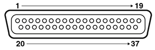
Pin number | Description | Pin number | Description |
|---|---|---|---|
1 | Channel 1 input | 20 | Channel 1 return |
2 | Channel 2 input | 21 | Channel 2 return |
3 | Channel 3 input | 22 | Channel 3 return |
4 | Channel 4 input | 23 | Channel 4 return |
5 | Channel 5 input | 24 | Channel 5 return |
6 | Channel 6 input | 25 | Channel 6 return |
7 | Channel 7 input | 26 | Channel 7 return |
8 | Channel 8 input | 27 | Channel 8 return |
9 | Channel 9 input | 28 | Channel 9 return |
10 | Channel 10 input | 29 | Channel 10 return |
11 | Channel 11 input | 30 | Channel 11 return |
12 | Channel 12 input | 31 | Channel 12 return |
13 | Channel 13 input | 32 | Channel 13 return |
14 | Channel 14 input | 33 | Channel 14 return |
15 | Channel 15 input | 34 | Channel 15 return |
16 | Channel 16 input | 35 | Channel 16 return |
17 | Reserved | 36 | Reserved |
18 | Reserved | 37 | Reserved |
19 | Reserved | Shell | Screen |
The thermistors for each channel connect between the CH input and CH return pins. The return signals are NOT zero volts and MUST NOT be connected to any zero volt signal, GND or screen. Do not connect the return signals to anything else apart from the thermistor.
NOTE: For more information regarding the set up and usage of axis and work piece sensors, please refer to the TEC installation guide (Renishaw part number H-1000-5105).
Stylus change rack (SCR) connector
The SCR200 stylus change rack is connected to the controller via a 6-pin miniature DIN socket. The pin numbers are illustrated and their functions are shown in the table.
SCR200 connector (view on rear panel)
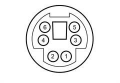
Pin number | Description | Pin number | Description |
|---|---|---|---|
1 | Reset | 4 | +5 V |
2 | Fault | 5 | 0 V |
3 | Inhibit | 6 | Reserved |
Shell | Screen |