Navigation
UCC T3 PLUS and UCC S3 troubleshooting
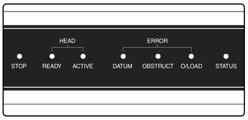
Front panel LEDs
UCC T3 PLUS or UCC S3 visual diagnostics

LED status key:
| LED | Description |
|---|---|
LED on | |
LED flashing off / on | |
LED flashing green / red | |
LED off | |
LED flashing red / blue |
Name | LED colour | Function |
|---|---|---|
STOP | PHC10-3 PLUS asserting PICS STOP when lit | |
STOP | PI 200 asserting PICS STOP | |
HEAD READY | Head ready for use when lit | |
HEAD ACTIVE | Head indexing when lit | |
DATUM ERROR | Head datum error when lit | |
OBSTRUCT ERROR | Head obstruct error when lit | |
O/LOAD ERROR | Head overload error when lit |
Name | LED colour | Function |
|---|---|---|
STATUS | No LED - no power to UCC T3 PLUS / UCC S3 or downloadable unable to start, power cycle and try again | |
STATUS | Continuous LED - problem with comms link - reboot UCC T3 PLUS or UCC S3 and configure IP | |
STATUS | Slow flash - waiting for download | |
STATUS | Continuous light - download successful | |
STATUS | Fast flash (5 Hz) - IP configuration mode | |
STATUS | Dual flash - controller booting | |
STATUS | Internal timeout - reboot UCC T3 PLUS or UCC S3 | |
STATUS | Fast flash (5 Hz) - communications error - reboot required | |
STATUS | Slow flash - scale error - reboot required | |
STATUS | Slow flash - problem with download - reboot required (check the file type is valid) | |
STATUS | Continuous LED - UCC T3 PLUS or UCC S3 overheated | |
STATUS | Slow flash - unit does not have controller ID - return to Renishaw | |
STATUS | Fast flash (5 Hz) - no controller ID in IP configuration mode - return to Renishaw |
NOTE: A scale error will cause the UCC T3 PLUS or UCC S3 to enter an error state which is not recoverable within a metrology application environment. If a scale error occurs it will be necessary to reinitialise the installation due to the possibility of lost scale counts and metrology being effected.
This section on troubleshooting is a guide to problems associated with the installation and integration of the PH10 system only. Refer to the 'PH10 PLUS installation and user's guide' (Renishaw part number H-1000-5070) regarding problems associated with normal operation of the PH10 system.
The UCC T3 PLUS or UCC S3 will assert PICS STOP under the following conditions:
Condition | Notes |
|---|---|
Overload error | Head has been overloaded when locked, causing it to unlock. |
Obstruct error | Head has been obstructed when moving to requested position or is unable to lock into it. |
Head disconnect | Head removed, cables disconnected, cable break |
Datum error | The head has failed to lock up correctly. |
Pressing and releasing the E-STOP button will clear the PICS STOP providing the cause has been addressed.
Use the tables below to identify problems you are experiencing with your PH10 PLUS system. If you experience problems which you are not able to identify or solve satisfactorily, please contact Renishaw for further advice.
No head movement in automatic mode:
Possible cause | Solution |
|---|---|
Cable / connection fault | Check connection and integrity of cabling between head and controller. |
No probe signal from PH10 PLUS:
Possible cause | Solution |
|---|---|
Cable / connection fault | Check connection and integrity of cabling between head and controller. |
Multiwire bypass connector not fitted | Fit a multiwire bypass connector which will permit a standard touch-trigger probe signal to reach controller. |
Multiwired probe in use (SP25M) | Check that the multiwire cable is correctly fitted to the head. Check that the trigger output to the CMM controller is connected to the multiwired probe interface. |
Poor measurement performance assiociated with the PH10 PLUS:
Possible cause | Solution |
|---|---|
Loose mounting of head | Ensure all mounting screws are tight and mounting to CMM is secure. |
Probe damping enabled during measurement | Ensure probe damping is not enabled during measurement moves. |
Stylus is too close to the surface before taking point | Increase standoff distance in program. |