Navigation
Installation procedure - TP200 probe
Mounting the probe body on the probe head
CAUTION: Take great care not to drop the probe when installing.
Mount the probe body on the probe head before fitting a stylus module.
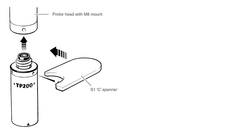
Probe heads with M8 connector
- Screw the threaded end of the probe body into the M8 connector, on the probe head, until it is finger-tight
- Fit the S1 ‘C' spanner (supplied) to the location holes and tighten by hand
- The recommended tightening torque is 0.3 Nm - 0.5 Nm
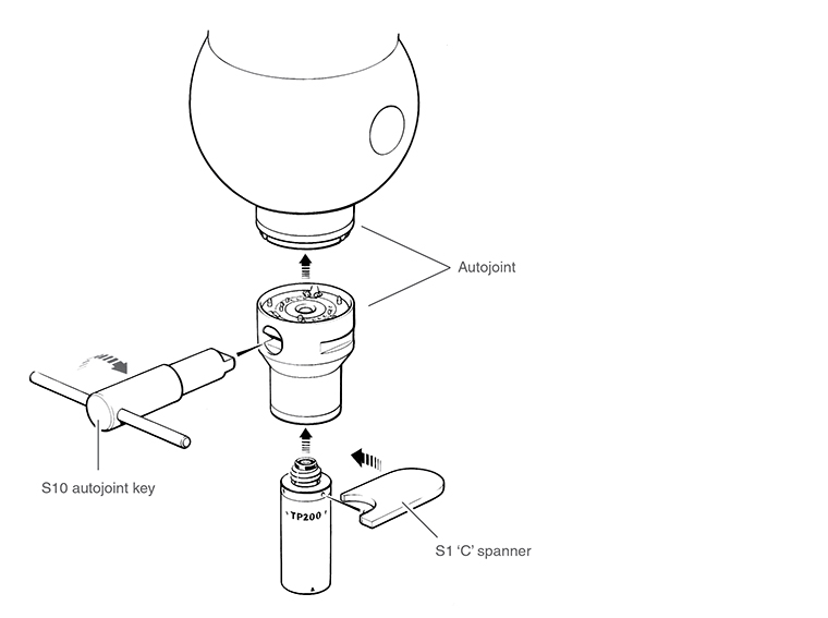
Probe heads with Renishaw autojoint
- Before fitting to the probe head, screw the probe body to a PAA series adaptor, as instructed above for M8 heads
- Locate the adaptor on the probe head and lock the autojoint using an S10 key
Assembling a stylus on a stylus module
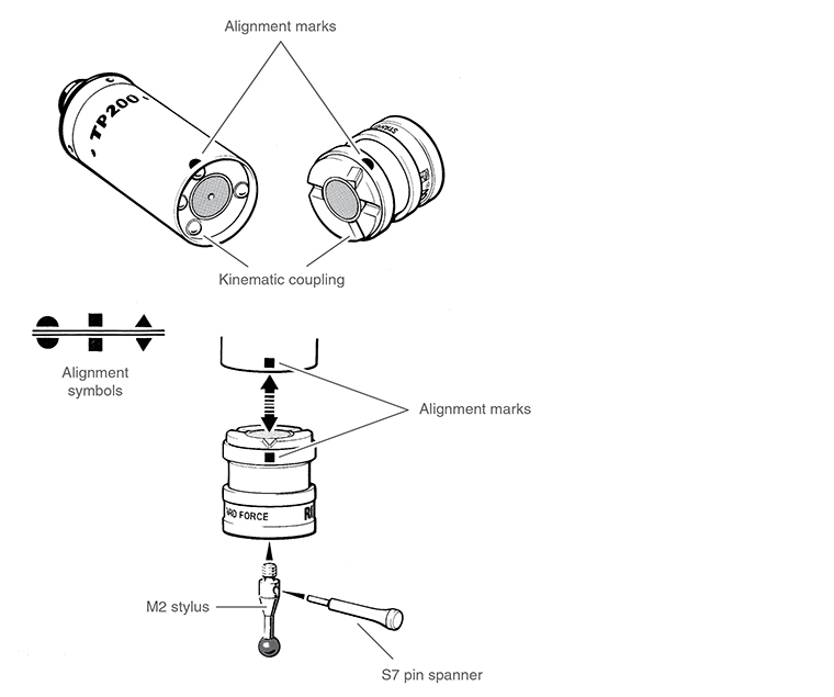
For a one-piece stylus, screw the stylus into the threaded mount on the stylus module until finger-tight. Fit an S7 pin spanner (supplied) into the stylus cross-hole and tighten using finger pressure to achieve the recommended torque of between 0.05 Nm and 0.15 Nm.
Where an offset or star stylus arrangement is to be used, assemble the arrangement loosely and offer the module up to the probe body to check alignment. Adjust the alignment with the module removed and tighten as described above using one or two S7 pin spanners as necessary.
Styli from the Renishaw GF (carbon fibre reinforced plastic) range must be tightened using the S20 tightening tool (supplied with the stylus kit). When tightening GF styli or extension pieces do not apply torque to the stylus stem. It may be necessary to use two S20 tools or S20 and S7 tools in combination to tighten adjacent threaded couplings. Refer to the instruction leaflet (Renishaw part number H-1000-4003) provided with the stylus kit.
Mounting the stylus module on the probe body
Visually examine the mating faces of the stylus module and the probe body for dirt or other contamination. Clean if necessary using the CK200 cleaning material (supplied), (refer to the 'Maintenance' section).
Offer up the stylus module to the probe body ensuring that the alignment symbols are matched. Allow the stylus module to engage under the pull of the magnetic force.
Reset the probe as described in the following section 'Resetting the probe'.
Resetting the probe
Press the RESET button, on the front panel of the PI 200-3 interface, for two seconds to reset the probe to the seated (armed) state.