Navigation
TP200 probe operation
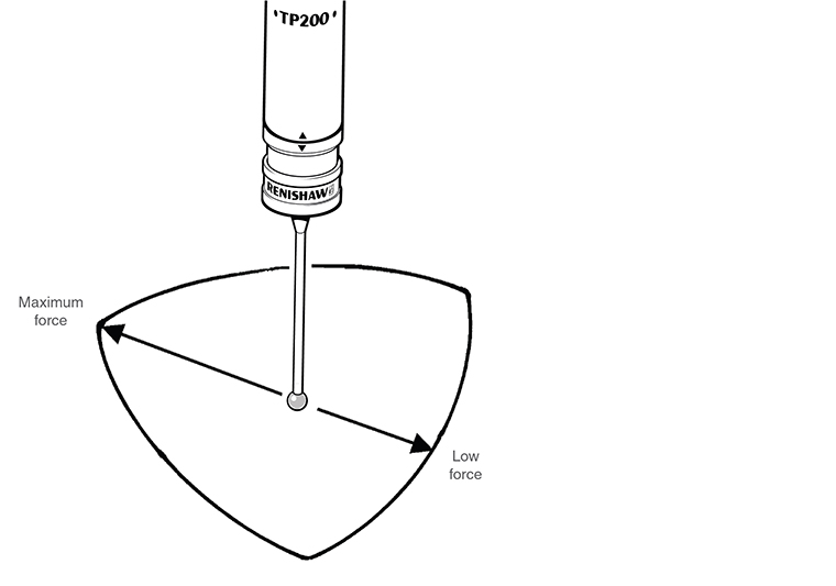
The TP200 probe has two normal operating states - armed or triggered. The probe should be in the armed state except for the moments when the stylus is deflected against the workpiece.
Probe armed
When the probe is armed (sometimes called ‘seated' or ‘reset') the following PI 200-3 front panel indicators will be ON:
- POWER ON
- TYPE - TP200
- PROBE - SEATED
Additionally, the probe head LED will be ON and the LEDs on the TP200 probe body will be OFF. The probe LEDs may sometimes glow slightly, indicating a low level of background vibration.
Probe triggered
When the stylus touches the workpiece the LEDs on the probe body turn ON brightly. The SEATED and probe head LEDs will turn OFF.
The probe should be allowed to remain in the triggered state only for the minimum time necessary to reverse the CMM motion and back-off from the workpiece.
If the probe remains in the triggered state for more than 10 seconds, drift of the stylus zero reference position will occur and the PI 200-3 will emit an audible warning. Back-off the probe from the workpiece and refer to 'Resetting the probe'.
Changing a stylus module manually
Ensure the CMM will remain stationary, in a safe condition.
Remove the stylus module and store safely.
To fit another module, refer to the 'Mounting the stylus module to the probe body' section.
When using MH8 or MIH probe heads, unlock and relock the head before resetting the probe.
Reset the probe, refer to the 'Resetting the probe' section.
Operation with a manual probe head
After manually re-orientating the probe when using PH1, MH8 or MIH probe heads, reset the probe. Refer to the 'Resetting the probe' section.
Stylus module selection
The SF module is satisfactory for the majority of applications and provides the maximum stylus carrying capability.
The LF module should be employed where the application necessitates the use of styli with ball diameters less than 1 mm, particularly the PS29R (Renishaw part number A-5000-7800), or where lower overtravel force will reduce the risk of marking or deflecting the surface of the workpiece.
The EO module is recommended for use when increasing the speed of the CMM may lead to stopping distances which exceed the overtravel range provided in the SF / LF modules.
Stylus selection
To obtain the best performance apply the following considerations when selecting and fitting a stylus:
- Use the shortest possible stylus length
- Minimise the mass of the stylus by using the types with ceramic or GF stems where possible - refer to the Renishaw stylus catalogue for further information
- Work within the recommended stylus limits
- Ensure that stylus balls, threads and mating faces are kept clean
- Tighten styli using only the tools provided
- Use the stylus changing facility to optimise the styli for accuracy and feature access
- Always qualify the styli at the gauging speed set for the part measurement program. If the speed is changed re-qualify the stylus tips
Recommended stylus limits
The absolute maximum stylus carrying ability of the TP200 probe is determined by the mass of the stylus and the distance from the stylus holder to the centre of gravity. The limits are:
Low force module | Standard force module |
|---|---|
3 g at 20 mm | 8 g at 50 mm |
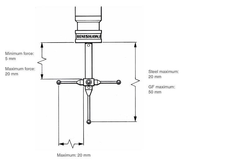
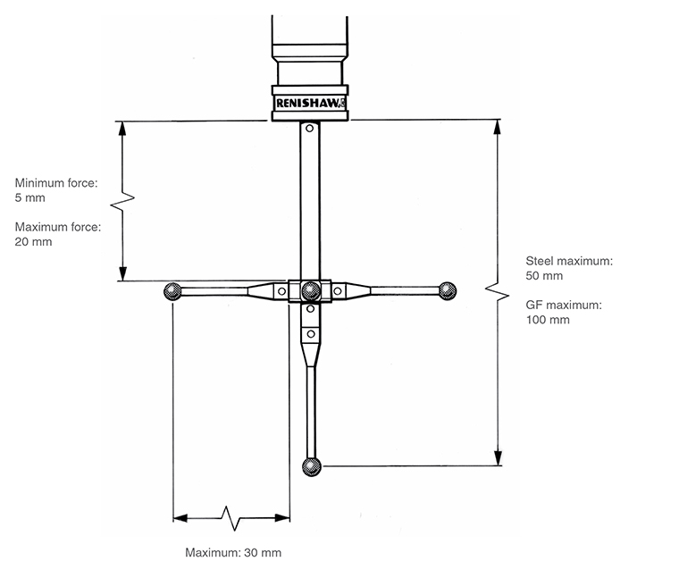
In practice, the stylus carrying is restricted by CMM vibration level, probe orientation and CMM controller flexibility. The recommended limits are given in the figures below.
It may be possible to exceed the recommended limits but the user is advised to conduct trials to establish the suitability for the application and the effect on measuring performance.
Recommended stylus limits - LF module:
Recommended stylus limits - SF / EO modules:
Trigger level
Under certain conditions, vibration may cause false ‘air' triggers during gauging and it may be necessary to reduce the probe sensitivity. False triggers may occur when large or heavy stylus arrangements are used, or where there is floor transmission from nearby machinery or vehicles.
- Trigger level 1 - the highest sensitivity mode, provides the best measuring accuracy
- Trigger level 2 - lower sensitivity to vibration but with a small loss of measuring accuracy
The trigger level is selected by switch 10 on the rear panel of the PI 200-3 interface:
- Level 1 - switch 10 DOWN
- Level 2 - switch 10 UP
The trigger level selection does not affect sensitivity when the probe is in damped mode.
Please consult your CMM supplier before making any adjustment to the PI 200-3 settings.
All stylus tips must be re-qualified after changing the trigger level.