Navigation
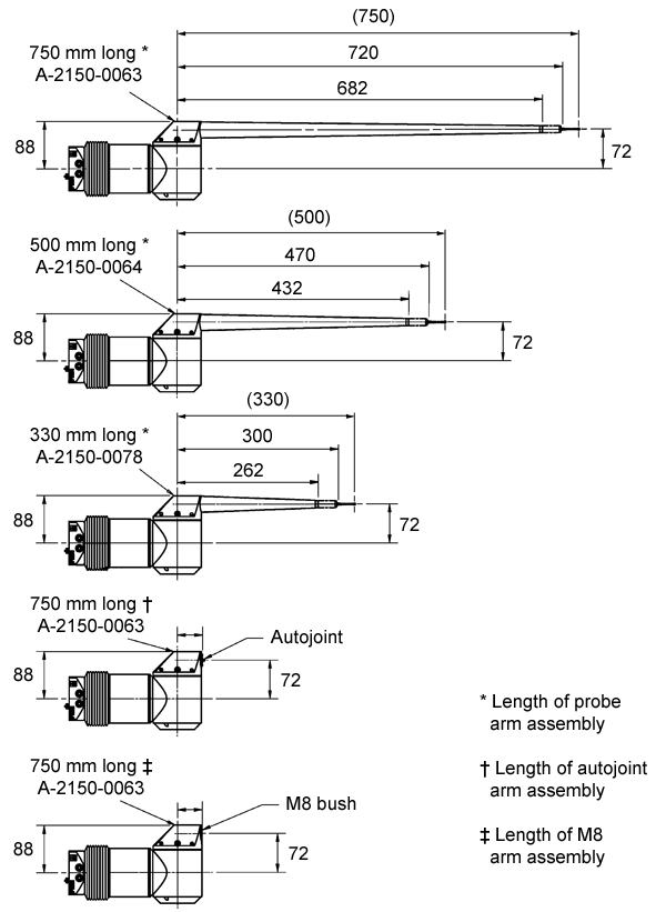
Probe arms
Dimensions of probe arm assemblies:
Changing probe arms
Refer to the ACR2 installation guide (Renishaw part number H-1000-4045) for information on automatic probe exchange.
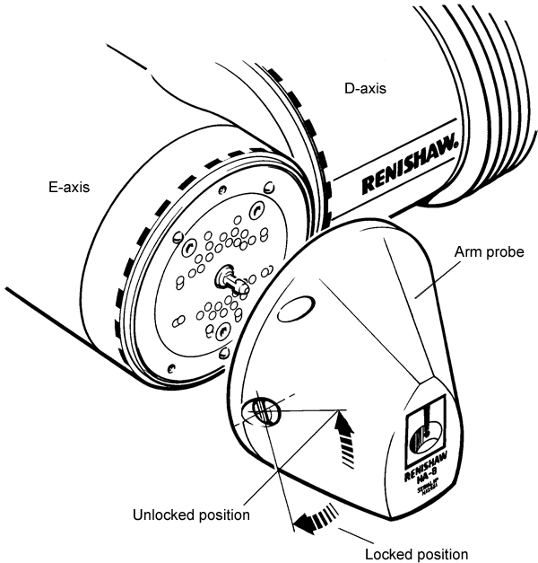
Manually changing a probe arm
NOTE: It is advised that no measurements should be made after a manual probe change. It is suggested that the probe should be unloaded and loaded in the autochange rack before use.
1. With the use of the autojoint key, ensure that the cam slot which operates the locking mechanism is in the unlocked '1 o'clock' position (see figure below).
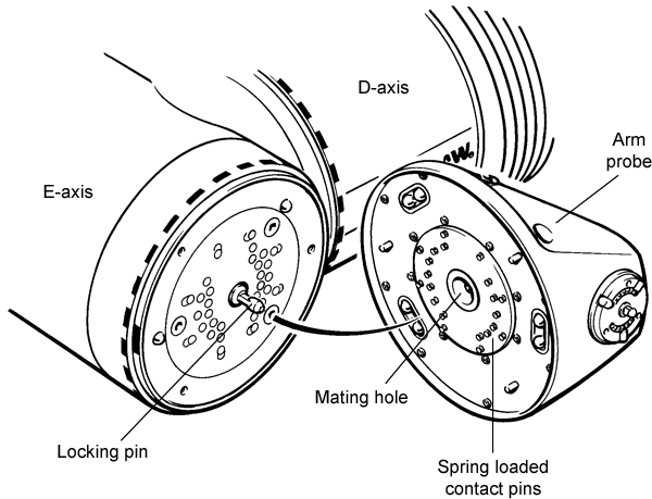
2. Place the probe arm in position, ensuring that the central pin on the head is aligned with the mating hole on the probe arm.
3. The alignment pin in the probe arm will engage and align the kinematic locations (see figure above).
4. Once aligned, turn the key to its locked '5 o'clock' position (see figure below).
The arm will not lock in position if the kinematics are not correctly engaged or the arm is in the wrong orientation.