Navigation
SFM surface finish modules
The SFM modules for the SFP2 probe system have been designed to suit the demands of specific parts and features encountered in a precision manufacturing environment.
Each SFM module is its own miniature measuring device, incorporating Renishaw's proprietary encoder system to transduce the motion of the stylus tip.
SFP2 module comparison chart
| Application | Diamond tip radius (µm) | Typical surface finish accuracy (of nominal Ra) * | Skid / stylus arrangement | Stylus holder compatibility | Lateral scanning capability | |
 | General purpose; engine block gasket face. | 2 or 5 | ±(5% + 15 nm) | Side-by-side | SFH-1, SFH-2 | Yes |
 | General purpose; engine block gasket face, lateral scanning of crank shaft bearing journals. | 2 or 5 | ±(5% + 15 nm) | Side-by-side | SFH-1, SFH-2 | Yes |
 | Scanning close to obstructive faces. | 2 or 5 | ±(5% + 15 nm) | Side-by-side | SFH-1, SFH-2 | Yes |
 | Scanning close to obstructive faces; lateral scanning of crankshaft bearing journals. | 2 or 5 | ±(5% + 15 nm) | Side-by-side | SFH-1, SFH-2 | Yes |
 | Awkward to reach pockets and groves. | 5 | ±(10% + 20 nm) | Side-by-side | SFH-1, SFH-2 | No |
 | Extended reach into confined areas; integrated bladed rotors (IBRs) with small blades. | 5 | ±(10% + 35 nm) | Side-by-side | SFH-1, SFH-2 | No |
 | Undercuts and grooves. | 5 | ±(10% + 20 nm) | Side-by-side | SFH-1, SFH-2 | No |
| Automotive engine valve guide ways. | 2 or 5 | ±(10% + 35 nm) | In-line (stylus lagging skid) | SFH-1 only | No |
 | Rotors, blisks and blades, especially fillet radii. | 2 or 5 | ±(10% + 20 nm) | In-line (stylus leading the skid) | SFH-1, SFH-2 | No |
 | Automatic transmission valve bodies, valve seats, minimum feature access (mm): Ø9 × 52 (max. depth). | 2 or 5 | ±(10% + 20 nm) | Stylus central to two-part skid | SFH-1 only | No |
 | Automatic transmission valve bodies, minimum feature access (mm): Ø9 × 122 (max. depth). | 5 | ±(20% + 60 nm) | Stylus central to two-part skid | SFH-1 only | No |
| Straight module for inspection of small groove features (type A skid). | 10 ** | 0.02 - 0.3 *** | Side-by-side | SFH-1, SFH-2 | No |
| Straight module with large radius skid for scanning with large cut-off values. | 2 or 5 | ±(5% + 15 nm) | Side-by-side | SFH-1, SFH-2 | No |


* Accuracy values are dependent upon a number of system variables. These include the machine size and configuration, scan orientation, condition of stylus tip, part fixturing system and environmental noise.
** Stylus tip radius (mm)
*** Feature depth range (mm)
 Data sheet: SFM-A1 (H-1000-2290)
 Data sheet: SFM-A2 (H-1000-2291)
 Data sheet: SFM-B1 (H-1000-2295)
 Data sheet: SFM-B2 (H-1000-2296)
 Data sheet: SFM-B3 (H-1000-2297)
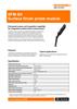 Data sheet: SFM-B4 (H-1000-2298)
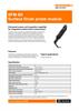 Data sheet: SFM-B5 (H-1000-2299)
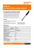 Data sheet: SFM-C3 (H-1000-2129)
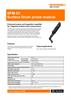 Data sheet: SFM-D1 (H-1000-2305)
 Data sheet: SFM-E1 (H-1000-2310)
 Data sheet: SFM-E2 (H-1000-2311)
 Data sheet: SFM-G1 (H-1000-2131)
 Data sheet: SFM-H1 (H-1000-2132)
Part number | |
REVO SFP2 kits | |
SFP2 combi kit #1 (A1 and A2 modules, single artefact) | A-5764-0001 |
SFP2 combi kit #2 (single artefact, no modules) | A-5764-0002 |
SFP2 combi kit #3 (A1 and A2 modules, triple artefact) | A-5764-0003 |
SFP2 combi kit #4 (triple artefact, no modules) | A-5764-0004 |
Single artefact kit (SFA1 and single artefact holding kit) | A-5764-0072 |
Triple artefact kit (SFA1, 2, 3 and triple artefact holding kit) | A-5764-0073 |
SFP2 probe and modules | |
SFM-A1 2 µm general purpose straight module (type A skid) | A1-D-02C90D |
SFM-A1 5 µm general purpose straight module (type A skid) | A1-D-05C90D |
SFM-A2 2 µm general purpose cranked module (type A skid) | A2-D-02C90D |
SFM-A2 5 µm general purpose cranked module (type A skid) | A2-D-05C90D |
SFM-B1 2 µm straight module with smaller skid for short lands (type B skid) | B1-D-02C90D |
SFM-B1 5 µm straight module with smaller skid for short lands (type B skid) | B1-D-05C90D |
SFM-B2 2 µm cranked module with smaller skid for short lands (type B skid) | B2-D-02C90D |
SFM-B2 5 µm cranked module with smaller skid for short lands (type B skid) | B2-D-05C90D |
SFM-B3 5 µm 90° module with smaller skid for pockets and grooves (type B skid) | B3-D-05C90D |
SFM-B4 5 µm cranked module with smaller skid for reach into confined areas (type B skid) | B4-D-05C90D |
SFM-B5 5 µm cranked module with smaller skid for reach into undercuts and grooves (type B skid) | B5-D-05C90D |
SFM-C3 2 µm straight module for small bores (type C skid) | C3-D-02C90D |
SFM-C3 5 µm straight module for small bores (type C skid) | C3-D-05C90D |
SFM-D1 2 µm 90° module for extra reach (type D skid) | D1-D-02C90D |
SFM-D1 5 µm 90° module for extra reach (type D skid) | D1-D-05C90D |
SFM-E1 2 µm long straight module with 2-part skid (type E skid) | E1-D-02C90D |
SFM-E1 5 µm long straight module with 2-part skid (type E skid) | E1-D-05C90D |
SFM-E2 5 µm long straight module with 2-part skid (type E skid) | E2-D-05C90D |
SFM-G1 Grooved engine bores prepared for PTWA coating (type G skid) | G1-D-10C30C |
SFM-H1 automatic transmission valve bodies, minimum feature access (mm): Ø9 × 122 (max. depth) (type H skid) | H1-D-02C90D |
SFM-H1 5 µm automatic transmission valve bodies, minimum feature access (mm): 9 122 (max. depth) (type H skid) | H1-D-05C90D |
Accessories | |
SFH-1 surface finish module holder | A-5764-0080 |
SFH-2 surface finish module holder | A-5764-0081 |
SFA1 3.0 SIN artefact (SFA1 plate with UKAS certificate) | A-5764-0060 |
SFA2 0.5 SIN artefact (SFA2 plate with UKAS certificate) | A-5764-0061 |
SFA3 0.4 ST artefact (SFA3 plate with UKAS certificate) | A-5764-0062 |
OFA optical flat artefact (* special product) | A-5764-3142 |
Single artefact holder mounting kit. Contains: SFAH-1 single plate holder, rack adaptor, leg adaptor, fixings for all options, tools | A-5764-0070 |
Triple artefact holder mounting kit. Contains: SFAH-2 triple plate holder, rack adaptor, leg adaptor, fixings for all options, tools | A-5764-0071 |
TFP tip find probe kit (including TP20 LF mod, stylus, PL24 cable) | A-5764-0063 |
MST module setting tool | A-5764-0091 |
System storage box | A-5764-0090 |