Navigation
Installing the system
Electrical requirements
See the 'Safety' section (page 7 of this document).
The ACC2-3 controller
It is recommended that the ACC2-3 is mounted to give a clear view of the front panel LEDs and to give easy access to the RESET button.
The weight of the ACC2-3 controller is 1.8 kg.
The ACC2-3 controller can be used in a 19-inch rack system or as a stand-alone unit.
Stand-alone
Four self adhesive feet are supplied with the unit for stand-alone use.
Mounting alone in a 19-inch rack
WARNING: In all installations ensure the ACC2-3 is disconnected from the mains supply during installation.
WARNING: Take care not to exceed the operation ambient of 50 °C around the unit. Do not install near sources of heat. Forced cooling may be required in final installation.
NOTE: In all installations use mounting screws supplied with this equipment. Do not replace with longer screws as damage could occur.
The following figure shows the ACC2-3 ready for mounting to a 19-inch rack:
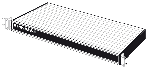
The rack mount bracket kit is part no. A-1018-0124.
System interconnection diagrams
The following figures show the main components of a Renishaw autochange system should be connected.:
ACC2-3 with PH10M PLUS and TP20
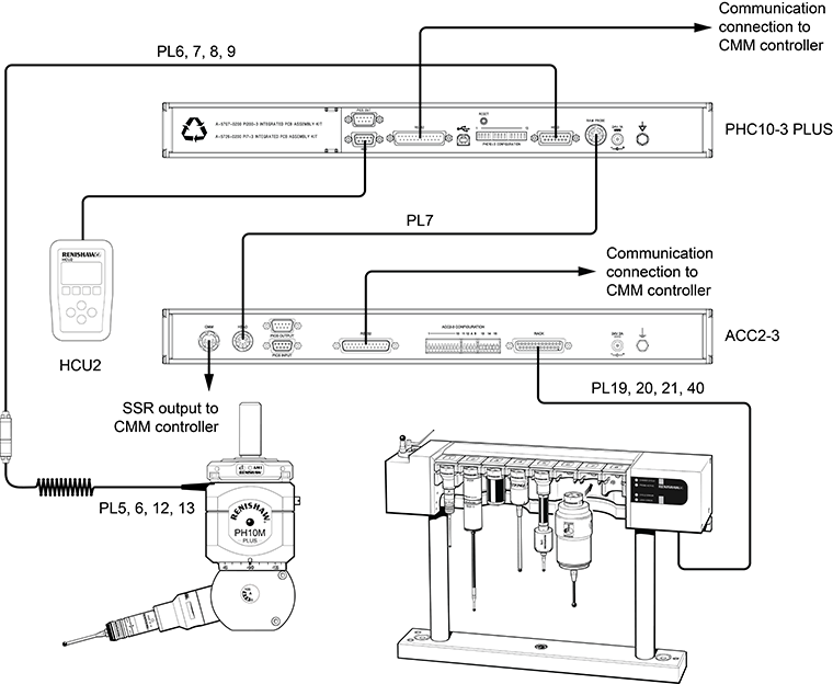
Switch settings for this arrangement:
Switch settings used with this arrangement are detailed in the following table. Switches that are not specified are configured by the CMM machine supplier.
SSR configuration Up | SSR configuration Down | |
|---|---|---|
PHC10-3 PLUS | - | 15, 16, 17, 18 |
ACC2-3 | 9 | - |
ACC2-3 with PH10M PLUS and TP20 or TP200
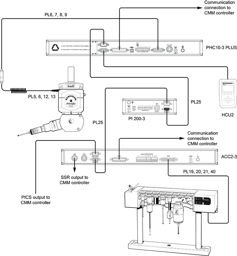
Switch settings for this arrangement:
Switch settings used with this arrangement are detailed in the following table. Switches that are not specified are configured by the CMM machine supplier.
PICS configuration Up | PICS configuration Down | SSR configuration Up | SSR configuration Down | |
|---|---|---|---|---|
PHC10-3 PLUS | 11, 15, 16, 17, 18 | - | 11, 15, 16, 17, 18 | - |
ACC2-3 | 9 | - | - | 9 |
PI 200-3 (V9+) | - | - | - | - |
PI 4-2 | - | - | - | - |
ACC2-3 with PH10M PLUS and TP7M
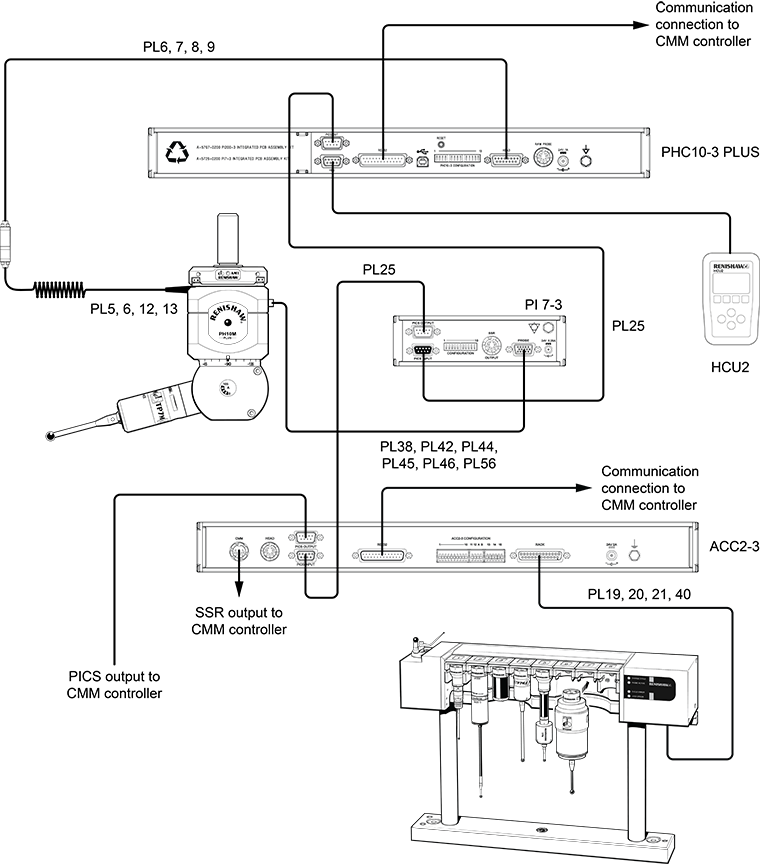
Switch settings for this arrangement:
Switch settings used with this arrangement are detailed in the following table. Switches that are not specified are configured by the CMM machine supplier.
PICS configuration Up | PICS configuration Down | SSR configuration Up | SSR configuration Down | |
|---|---|---|---|---|
PHC10-3 PLUS | 11, 15, 16, 17, 18 | - | 11, 15, 16, 17, 18 | - |
ACC2-3 | 9 | - | - | 9 |
PI 7-3 | 3 | - | 3 | - |