Navigation
The ACC2-3 autochange controller
Description
The ACC2-3 autochange controller is the intelligent part of the system. It handles the communications to and from the CMM controller, controls the ACR1 autochange rack, and multiplexes and interfaces the head and datum probe signals.
The ACC2-3 has been designed for simple installation. It is functionally compatible with any ACC1 or ACC2 installation but incorporates several new features and a new specification.
Control of the autochange system can be carried out in two different ways:
- RS232 (serial) communications from the CMM controller (see 'Stand-alone mode' section).
- Stand-alone: no communications are required as the system works on a series of time-outs after detected events (see 'Interfaces' section).
Front panel
The following figure shows the arrangement of the ACC2-3 front panel. Descriptions of the functions of the switch and LEDs follow.

1 POWER ON LED (green)
Powered from an internal power rail, this LED indicates that the unit is switched on.
2 PROBE SEATED LED (yellow)
Indicates the status of the selected probe. When the probe interface circuit is active, this LED will be ON. In this condition the LED will be OFF when the stylus is deflected.
NOTE: This LED is only operational when the internal probe interface is selected.
3 RACK READY LED (yellow)
Indicates the status of the rack. The LED is OFF when the rack is active. A flashing LED indicates that the system is in datum mode 1 (see 'Operating modes' section, mode 6).
4 RACK ACTIVE LED (yellow) *
Indicates that the rack is performing a lock or unlock procedure. A flashing LED indicates that the system is in datum mode 2 (see 'Operating modes' section).
5 LOCK ERROR LED (red) *
Indicates that a fault has occurred during a lock or unlock procedure.
6 OVERTRAVEL ERROR LED (red) *
Indicates that the rack has been overtravelled or an excessive entry speed condition has been detected.
7 STOP LED (red)
Indicates that the ACC2-3 has asserted the PICS STOP signal following a critical failure.
* Various combinations of these LEDs are used to indicate other fault conditions (see 'Operating modes' section, 'Mode 4 - Error mode).
8 RESET
The RESET switch initiates a complete software restart. It is used for resetting the system after a collision, or for putting the system into or out of datum mode 1 (mode 6). To take effect, the button must be pressed for at least 100 ms.
Rear panel
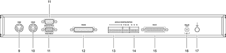
9 CMM output connector (5-pin 180° DIN socket)
This is the conventional (non-PICS) output socket. The pin numbers and associated signals are given in the table below.
CMM output pin numbers:
Pin number | Signal | Comment |
|---|---|---|
1 | Probe output * (normally high) | High or open circuit for a seated probe |
2 | 0 V digital | This signal is the ground reference for the other signals of this interface. It must not be connected to the cable screen (the cable screen must be connected to the body of the connector). |
3 | Probe output * (normally low) | Low or short circuit for a seated probe. |
4 | Not used | - |
5 | External reset | This input signal produced a software restart when asserted for 100 ms (or more) during any mode except a lock or unlock routine. When the signal is pulled LOW, restart is requested. |
Chassis | Screen | The body of the connector is connected to the ACC2-3 chassis earth. The output cable screens can be connected to this point if required. |
* TTL and OCT outputs must be taken from pins 1 or 3 with reference to 0 V (pin 2).
SSR output is between pins 1 and 3 and these outputs are isolated from 0 V.
10 Head input connector (7-pin DIN socket)
This is the conventional (non-PICS) probe input connector. It may be used to connect the ACC2-3 to the probe head controller (PHC10-3 PLUS).
The pin numbers and associated signals are given in the table below.
Head input pin numbers:
Pin number | Signal | Comments |
|---|---|---|
1 | LED cathode | This output controls the probe LED. When this output is LO the LED will be ON. |
2 | Screen | Cable screen: this is the connection between the cable screen and ACC2-3 chassis ground. |
3 | LED anode | This is the power output to drive the probe LED. This output will supply around 10 mA to the probe LED when ON. |
4 | Touch probe return (0 V) | These are the input signals from the the probe contacts. Closed contacts indicate a seated probe - open contacts indicate an unseated probe. |
5 | Touch probe signal (HI) | These are the input signals from the the probe contacts. Closed contacts indicate a seated probe - open contacts indicate an unseated probe. |
6 | Inhibit return (0 V) | Inhibit and return: this input pair controls the inhibition of the probe interface circuit. When INHIBIT (HI) is connected to 0 VA (LO) the probe interface circuits is inhibited. |
7 | Inhibit signal (HI) | Inhibit and return: this input pair controls the inhibition of the probe interface circuit. When INHIBIT (HI) is connected to 0 VA (LO) the probe interface circuits is inhibited. |
Chassis | - | This is the body of the connector which is connected to the ACC2-3 chassis. |
11 PICS input and output connectors
PICS (Renishaw's product interconnection system) is used for real time two-way communication of status and command signals between Renishaw units and the CMM controller.
Input and output of the PICS signals is via 9-way D-type connectors. PICS is sensitive to the order in which Renishaw units are connected (i.e. input must come from another Renishaw interface, and output must be directly to the CMM controller).
The following table describes the pin numbers and signal functions.
PICS pin numbers and signal terminations:
| Pin number | Signal |
|---|---|
1 | STOP (in / out) |
2 | PROBE POWER OFF (PPOF) (in / out) |
3 | 0 V |
4 | Reserved for Renishaw use |
5 | SYNC output (probe trigger) |
6 | HALT output |
7 | PROBE DAMPing (PDAMP) (in) |
8 | LED OFF (in) |
9 | - |
Body | Screen |
For a full description see the product interconnection system guide (Renishaw part number H-1000-5000).
12 RS232 interface connector (25-way D-type plug)
This is the serial input / output communications link to the CMM controller. The pin designations and signal names are given in the table below.
RS232 pin numbers and signals:
Pin number | Signal |
|---|---|
1 | Screen |
2 | Transmitted data to measuring machine controller (MMC) |
3 | Received data from measuring machine controller (MMC) |
4 | RTS (request to send) to MMC |
5 | CTS (clear to send) from MMC, connect pin 4 to pin 5 if CTS is not output from MMC |
7 | Signal ground (common) |
10 | DTR (data terminal ready) to MMC |
For a detailed description of RS232 operation see 'RS232 communications' section.
13 Configuration switches (1 to 12)
These are used to set the communication parameters and are described in the 'RS232 communications' and 'Interfaces' sections.
14 Output switches
The conventional (non-PICS) probe output can be configured using these three switches.
The available outputs are SSR (solid state relay), OCT (open collector transistor) or TTL (transistor-transistor logic) with both true and complement outputs selectable for each output.
The following table shows the output options.
Output switches:
Switch 13 | Switch 14 | Switch 15 | Output format and SK3 pins |
|---|---|---|---|
X | Down | Down | SSR normally closed on pins 3 and 1 |
X | Down | Up | SSR normally open on pins 3 and 1 |
Down | Up | X | OCT normally LO on pin 3 |
Down | Up | X | OCT normally HI on pin 1 |
Up | Up | X | TTL normally LO on pin 3 |
Up | Up | X | TTL normally HI on pin 1 |
X = switch may be up or down
The two TTL compatible outputs are generated using current limited (30 mA approximately) open collector drives, with 2K7 pull-up resistors to +5 V.
The two OCT outputs are generated using current limited open collector drives. The maximum sink current is 30 mA. The maximum collector voltage is +30 V (dc or ac).
The specification of the SSR output is as follows.
SSR output specification:
Contact ratings | +50 V max, ±30 mA max (ac or dc) |
|---|---|
Contact ON resistance | 5 (maximum) |
OFF state leakage current @ 25 V | 0.006 µA |
OFF state leakage current @ 50 V | 60 µA |
Turn ON time (with VL = 20 V, RL = 1K0) | 10 µs max |
Turn OFF time (with VL = 20 V, RL = 1K0) | 15 µs max |
Both contacts isolated from ACC2-3 0 V.
15 Rack connector (25-way D-type socket)
This is the only connection between the ACC2-3 and the ACR1, and carries all the necessary power and signal lines. The pin numbers, signal designations and descriptions are given in the table below.
Rack connector pin numbers and functions:
Pin number | Designation | Description |
|---|---|---|
1 | RACK MOT | Supply to ACR1 motor |
2 | RACK MOTRET | 0 V return for ACR1 motor |
3 | CABLE SENSE | Rack cable sense return |
4 | POT F/B | ACR1 screwdriver' position feedback |
5 | R.DETECT | ACR1 rear lightbeam signal |
6 | R.PROBE CONTACT 2 | Rack probe contact 2 |
7 | RACK REF | Precision reference voltage for ACR1 position potentiometer |
8 | IND 4 | ACR1 'Lock Error' indicator |
9 | 0 V RACK | ACR1 0 V |
10 | IND 0 | ACR1 'Change Cycle' indicator |
11 | RESERVED | Future expansion |
12 | RESERVED | Future expansion |
13 | - | - |
14 | RACK MOT | Supply to ACR1 motor |
15 | RACK MOTRET | 0 V return for ACR1 motor |
16 | CABLE SENSE | Rack cable sense output |
17 | F.DETECT | ACR1 front lightbeam signal |
18 | R.PROBE CONTACT 1 | Rack probe contact 1 |
19 | O/T 1 | ACR1 overtravel signal |
20 | IND 1 | ACR1 'Probe Active' indicator |
21 | IND 3 | ACR1 'Cycle Error' indicator |
22 | +15 V | Supply to ACR1 circuits |
23 | GND SENSE | Ground sense |
24 | RESERVED | Future expansion |
25 | RESERVED | Future expansion |
16 DC power jack
17 Equipment bond point
RS232 communications
SETTING UP
RS232 communications are selected by setting switch 11 ON (down) and switch 12 OFF (UP). These switches are on the rear panel.
The baud rate is controlled by switches 1 to 3 and the range available is given in the table below.
Selection of the internal (conventional) interface or PICS operation is performed by switch 9, UP for PICS, DOWN for conventional interface.
Switches A and B are reserved for Renishaw use. To enable normal operation of the ACC2-3, they must both be set in the DOWN position.
The following table defines the switch positions for RS232 operation.
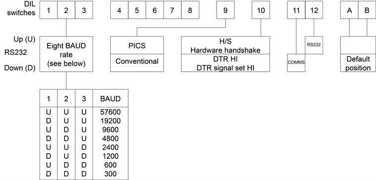
NOTE: These switches are only read on power up or after a software reset. If any settings are changed, the ACC2-3 must be switched OFF, then ON, or the RESET switch operated to act on these changes.
Operation
The data format is:
“7 + 1 E”
one start bit
seven data bits
one parity bit
one stop bit for transmitted and received data
No parity checks are performed on receive.
The parity bit is set to Even Parity on transmit.
All communications are full duplex.
The software is capable of receiving data terminated with a carriage return (CR) or with a CR and a line feed (LF). In the latter case the LF is ignored.
All transmissions are terminated by a CR and LF.
The request to send (RTS) active high output is used to indicate that a message is ready for transmission.
RTS will be cleared after the LF of the last message has been transmitted.
The clear to send (CTS) active high input is checked before transmitting each byte to ensure that the CMM is ready to receive. If the active signal is not received within 10 seconds of asserting RTS, STOP will be applied. The STOP signal will be released when CTS becomes active.
Communication of data is possible if RTS has been connected to CTS by a user.
If the hardware handshake option is selected (switch 10), data terminal ready (DTR) will be set when the ACC2-3 is ready to receive a command.
Receipt of an X OFF (control S, 13 hex) command will halt the transmission of data. Transmission will be resumed upon receipt of an X ON (control Q, 11 hex) command. These commands do not affect any process other than transmission of data (e.g. time-outs are unaffected).
Any commands received before the completion of the previous command will be ignored. This situation will be reported as below:
CNA (command not accepted): Present status 5 (CR) (LF)
e.g. Y5 - CMM control mode, last command ignored
The interface is configured such that the product is a ‘data terminal equipment' according to the EIA RS232 definition.
The pin functions of the RS232 connector are shown in the following table:
RS232 pin numbers and functions
Pin number | Function |
|---|---|
3 | Receive (input) |
2 | Transmit (output) |
20 | DTR (output) |
5 | CTS (input) |
4 | RTS (output) |
7 | SIGNAL GND |
1 | PROTECTIVE GND |
NOTE: The cable screen must be connected to pin 1 and the cable shell. The signal 0 V must be connected to pin 7. The cable screen must not be connected to pin 7.
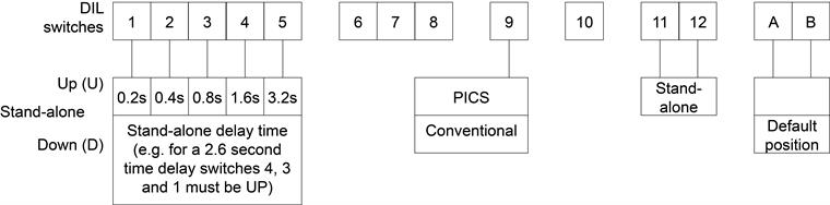
Stand-alone mode
Stand-alone mode is selected by setting switch 11 and switch 12 (on the rear panel) OFF (UP) (see table below).
Switches A and B are reserved for Renishaw use. To enable normal operation of the ACC2-3, they must both be set in the DOWN position.
In stand-alone mode the system can be used with no intervention or communication from the CMM controller. This can be an advantage when retrofitting an autochange system to an existing CMM or if there are no spare communication ports on the CMM controller.
The system functions by using the ability of the ACR1 to detect whether a pick-up or put-down operation is required, and after a selectable time delay locks or unlocks the autojoint.
The sequence of operations is as follows:
a) When the lid of the port starts to open, one of two infra-red beams is broken. Which one is broken first depends on whether an empty autojoint, or one loaded with a probe, is entering the port.
Having detected what is entering the port, the ACC2-3 disables the probe interface and ensures that the 'screwdrivers' are set correctly to receive the autojoint.
b) When the second beam is broken, a time delay is started after which the screwdrivers are driven to their other position. The period of this delay is selectable between 0 and 6.2 seconds by means of DIL switches 1 - 5.
c) The ACC2-3 now waits for the autojoint to leave the ACR1 and detects whether it has picked up a probe by the order in which the beams are made. If a probe has been picked up, the interface is enabled by the making of the second beam, but if an empty autojoint is leaving the ACR1 the interface remains disabled.
If any fault or problem occurs during the change cycle the ACC2-3 will communicate this to the CMM by signalling a probe triggered state and illuminating the appropriate LEDs on the ACC2-3 and ACR1.
Although no communications are necessary for stand-alone operation, the communication interface defaults to 9600 baud RS232 operations. If required for software development or fault finding purposes, system operation can be monitored.
It is also possible to send commands in this state, but note that the G command is not operative.
Selection of the internal (conventional) interface or PICS operation is performed by switch 9 UP for PICS, DOWN for conventional interface.
The system can be reset by either manual operation of the front panel switch or by operation of the external reset line (pull low pin 5 of the CMM output connector).
NOTE: In this mode it is not possible to pick up a probe extension (eg PEM), unless it is already connected to a probe, because the interface cannot be inhibited via the communications link.
Interfaces
Interfacing the probe signal from the CMM can be implemented in one of two ways:
- by the ACC2-3's internal (conventional) probe interface - see 'Internal interface' below
- by PICS connection to an external interface - see 'PICS' below
The internal interface is suitable only for the autochanging of conventional two-wire touch-trigger probes. However, for new designs and more complex probing systems, it is strongly recommended that PICS is used.
An advantage of PICS is that it is a real-time, two-way, standardised communication system.
PICS requires only one output from the CMM controller to control and monitor Renishaw equipment. This is possible because not only does the CMM controller send and receive information from Renishaw equipment, but also the individual controllers communicate with each other (eg the 'probe power OFF' (PPOFF) command can be initiated by both a PHC10 or PHC10-2 probe head controller and the ACC2-3 as well as the CMM controller). This considerably simplifies the control software, leaving the CMM controller free to perform other tasks.
Internal interface
This is a conventional touch-trigger probe interface housed inside the ACC2-3. The signal from the probe is connected to the ACC2-3 via the 7-pin DIN 'HEAD' connector on the rear panel (see section '15 Head input connector (7-pin DIN socket)) and the interfaced signal is connected to the CMM controller via the 5-pin DIN ‘CMM' connector (see section '14 CMM output connector (5-pin 180° DIN socket)).
The interface is inside the ACC2-3, because the probe signal must be switched with the datum probe signal when the system is in datum mode 2 (mode 6).
The various output formats are defined in section '13 Output switches'.
NOTE: It is possible to use the ACC2-3 just as a two-wire probe interface, with no ACR1 connected, by linking pins 9 to 23 on the 25-way D-type rack connector.
PICS
Using this method the CMM probe signal is connected to an external PICS-compatible interface (e.g. PI 7-3 or PI 200-3) and the output is connected to the
ACC2-3 via the ACC2-3 PICS input connector (see section '9 PICS input and output connector'). The CMM probe signal passes straight through to the CMM controller unless the ACC2-3 is in datum mode 2 (mode 6, see section 'Mode 6 - Datum mode').
In datum mode 2 the ACC2-3 applies PPOFF (probe power OFF) to inhibit the external interface, connects the datum probe output to the SYNC line and directly controls the head LED during a change cycle.
During a change cycle any externally applied damping (PDAMP) signal, is overridden by the ACC2-3, to prevent the interface probe selection from being inhibited.
The ACC2-3 passes on all necessary received PICS signals to the other products in the system.
The only PICS signals asserted by the ACC2-3 are SYNC, probe power OFF (PPOFF), LED OFF and STOP. The use of these signals is limited to those operations defined in this document.
If STOP is asserted by another Renishaw product or the CMM, any motion of the screwdriver blades will be inhibited (except for lock and unlock routines whilst in error mode - mode 4). If the STOP signal is applied during a blade move, the blades will be commanded to the unlock position. If STOP is subsequently released the ACC2-3 will continue to function normally.
Any other process is not affected by the assertion of an externally generated STOP signal.
The information given in this section is specific to ACC2-3. A more general definition of PICS, its connectors and signals is given in the PICS installation guide (Renishaw part number H-1000-5000).