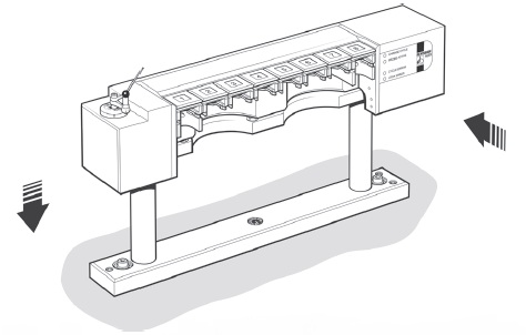
Navigation
Datuming the rack
NOTE: The ACR1 must be mechanically aligned prior to datuming the rack. Please refer to the autochange system user's guide (Renishaw part number H-1000-5090) for details.
Suggested datuming method
This is a suggested datuming method for the ACR1. You may find more suitable techniques depending upon your CMM and software.
To datum the rack you must take three sets of measurements:
- Set the rack datum probe as the origin
- Determine the port centrelines and heights
- Determine the probe head centreline and base height
The methods for these three procedures are given below.
Set the rack datum probe as the origin.
1. Fit a 2 mm diameter stylus (minimum length 20 mm) to a touch-trigger probe. If the probe has an M8 thread, screw the probe into an autojoint adaptor (PAA) and tighten.
2. Lock the autojoint on to the probe head using the joint key.
3. Gauge the 8 mm datum stylus in four positions to define its centre point.
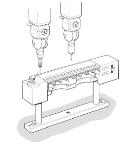
4. Assign this centre point as the origin for all further measurements.
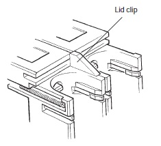
Determine port centrelines and heights
1. Ensure that all the ports are empty.
2. Insert the four lid clips at the joints of ports 1 and 2, 3 and 4, 5 and 6, and 7 and 8.
3. Select datum mode (see section 'Mode 6 - Datum mode').
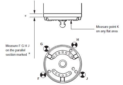
4. Find the port centre by gauging points A, B and C on a semi-circular portion of port 1.
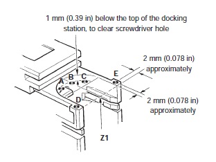
NOTE: If possible, four or five points should be used to find the port centre. If three points are used, probing close to the centre of the semi-circle should be avoided, as slight distortions can occur near the screwdriver hole. Ignore the Z co-ordinates.
5. To find the average port top surface height (Z1) gauge points D and E.
6. Repeat the centre line and surface height measurements for ports 2 to 8.
Determine head centreline and base height
1. Unlock and remove the autojoint adaptor from the probe head.
2. Remove all lid retaining clips.
3. Select datum mode (see 'Mode 6 - Datum mode).
4. To find the probe head centreline, gauge points F, G, H, and J on the outside diameter of the probe head, using the datum stylus on the datum probe.
Calculating docking height
The docking height (DH) is the height at which the probe head enters and exits a port when carrying a probe:
WARNING: The following calculations assume a stylus ball diameter of 2 mm.
DH = – (Z1 + Z2 + 6.65) mm
where:
the minus sign shows that the height DH is below the level of the origin (the datum probe stylus ball)
Z1 = average port height ((D+E) / 2)
Z2 = height to probe head base (point K)
6.65 = compensation value (see WARNING above) which ensures that the correct height is reached, derived by use of the following formula:
datum probe stylus ball radius + head / joint overlap + TP2 stylus ball radius
(if not already compensated for by the software)
Example: = 4 + 1.65 + 1
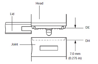
When entering and leaving a port without a probe, the head is set to a height (DE) which is 7 mm higher than DH to avoid collision:
DE = DH + 7 mm
Height DE ensures that the probe head pushes back the port lids by their upper surface.
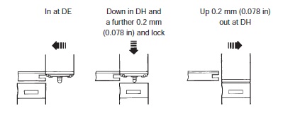
Loading procedure
1. Enter the port at 90° to the ACR1 at height DE, and push back the lid until the probe head centreline matches the port centreline.
2. Lower the head to the docking height DH, and then by a further 0.2 mm (0.078 in). The ACR1 locks the joint when instructed by the CMM.
3. Raise the probe head by 0.2 mm (0.078 in) then exit the port at height DH in the same plane as step 1.
WARNING: Due to the forces exerted by the autochange operation on the head, it is strongly recommended that the head is unlocked and re-locked immediately after picking up a probe, in order to maintain repeatability.
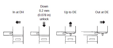
Unloading procedure
1. Enter the port at 90° to the ACR1 at height DH and push back the lid until the head centreline matches the port centreline.
2. Lower the head by 0.2 mm (0.078 in) and unlock the joint. The rack unlocks the joint when instructed by CMM.
3. Lift the head to height DE.
4. Exit the port at height DE in the same plane as step 1.
CAUTION: If a probe or extension bar is manually locked (using a joint key), it is advisable to lock it fully to the cam end stop, then back the screwdriver slot off by approximately 5. If this is not done, it is unlikely that the probe will dock satisfactorily into the ACR1. Should the motorised head overload whilst the rack screwdriver is turning, instruct the head controller to re-lock the head before continuing. This can be done manually, or under program control by the measuring machine computer.
Docking parameters
Speed
Entry speed depends upon the screwdriver position. If you can be certain that the screwdriver is positioned correctly, a speed of up to 60 mm/sec (2.36 in/sec) can be used. Otherwise the recommended maximum speed is 5 mm/sec (0.19 in/sec), to allow the screwdrivers to be corrected before they are engaged.
If the system is being used only to change probes, the screwdriver blades will naturally be in the correct position, but if PEMs are being used the screwdriver blade position may need to be corrected. This can be achieved by a slow rack entry speed of less than 5 mm/sec (0.19 in/sec), or by a separate instruction before entering a change cycle.
Overtravel
The ACR1 is restrained in the Y-axis but is free to move in the +X and –Z axes. There is a crash protection of 7 mm (0.27 in) in both axes. An opto switch tells the CMM to stop after 0.5 mm to 1.5 mm (0.019 in to 0.06 in) of overtravel. The remainder of the movement is for safety.
Tolerances
The CMM must position the head / autojoint to within ±50 µm (0.002 in), in all three axes, of the true park position. The CMM quill/shank mounting face must be within 0.1° of the true position relative to the machine axes. This is achieved by the alignment procedure.
The ACR1 is pre-loaded to approximately 10 N (2.25 lbf) to ensure that it repeatably returns to its 'at rest' position. This means that the CMM must exert a force greater than 10 N (2.25 lbf) to overtravel the rack. When set for horizontal operation an additional 10 N (2.25 lbf) pre-load is added to compensate for the weight of the docked probes and extension bars.