Navigation
The ACR1 autochange rack
Description
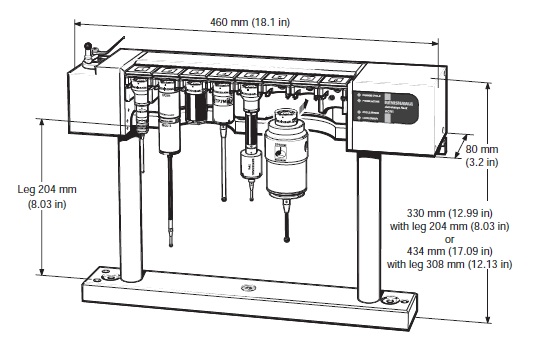
The autochange rack or ACR1 is the part of the system which is located within the CMM working volume. It is powered and controlled by the ACC2-3 via a rack cable which can be up to 30 metres (98 ft) long.
The ACR1 can store up to eight probe and extension bar combinations which can be exchanged automatically by the CMM.
ACR1 assembly
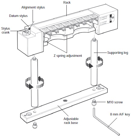
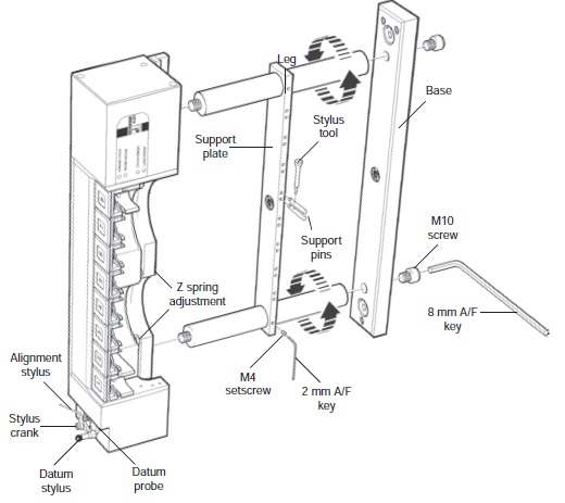
The ACR1 is fixed to the CMM using a mounting kit. This consists of an adjustable rack base and supporting legs for horizontal mounting (see section 'Rack assembly - horizontal mounting') with a support plate and pins for vertical mounting (see section 'Rack assembly - vertical mounting').
NOTE: ACR1 should not be left standing without fully fitting it to the bed of the machine as it is top heavy and likely to fall over.
Rack assembly - horizontal mounting
1. Separate the rack base into cover and base by removing the two screws shown.
2. Mount base to bed of machine.
3. Fit the datum stylus on to the stylus crank.
4. Secure the stylus crank and alignment stylus to the datum probe using the screw provided, and align the assembly.
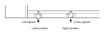
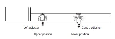
5. Two Z spring adjusters are provided. When mounting the rack horizontally, ensure that the centre adjuster is in the upper position and that the left hand adjuster is in the lower position.
To move the adjuster from the upper to lower position or from the lower to upper position:
a) Insert the joint key into the required adjuster at the bottom of the rack subframe.
b) Push the key towards the rack.
c) Turn the key anti-clockwise through 90° and release.
6. Screw the selected legs (104 mm [4.09 in] or 204 mm [8.03 in]) into the stubs on the underside of the rack. Additional legs can be screwed together to increase the height of the rack if necessary.
7. Tighten the legs by hand.
8. Attach the rack base cover to legs using the 10 mm screws and 8 mm Allen key provided.
9. Fit the completed assembly to the CMM table.
Rack assembly - vertical mounting
1. Separate the rack base into cover and base removing the two screws shown.
2. Mount base to pillar on machine.
3. Fit the datum stylus on to the crank.
4. Secure the crank and alignment stylus to the datum probe using the screw provided, and align the assembly as shown.
5. Two Z spring adjusters are provided. When mounting the ACR1 vertically, ensure that the centre adjuster is in the lower position and the left hand adjuster is in the upper position.
To move the adjuster from the upper to lower position or from the lower to upper position:
a) Insert the joint key into the required adjuster at the bottom of the rack subframe.
b) Push the key towards the rack.
c) Turn the key anti-clockwise through 90° and release.
6. Screw the selected legs into the stubs on the underside of the rack. Additional legs can be screwed together to increase the height of the rack if necessary.
7. Tighten the legs by hand.
8. Slide the support plate over the legs, ensuring that the label is aligned as shown. When the support plate is in a suitable position, tighten the two M4 set screws using a 2 mm A/F hexagonal key.
9. Fit the support pins using the stylus tool. When the rack is used in the vertical position, support for long extensions is recommended. Fit a support pin to the top or bottom support pin hole depending on the diameter of the extension to be used and its port location. Fit to the top support pin hole for extensions with a 13 mm diameter (PAA2, PAA3). Fit to the bottom support pin hole for extensions with a diameter of 25 mm (SP25M, PEM3).
10. Attach the rack base cover to the legs using the 10 mm screws and 8 mm Allen key provided.
11. Fit the completed assembly.
Rack mounting kit
The rack mounting kits contain the necessary components to mount the ACR1 on to a CMM:
1. The basic kit contains the parts necessary for horizontal mounting. The components are as follows:
- Adjustable rack base × 1
- 204 mm (8.03 in) legs × 2
- M10 × 16 mm socket head screws × 2
- Hexagonal keys
2. The vertical kit contains the parts necessary for vertical mounting. The components are as follows:
- Support plate × 1
- Support pins × 8
- Hexagonal keys
Also available separately are additional 100 mm and 200 mm legs.
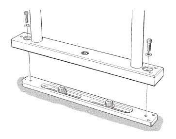
Adjustable base
For smooth wear-free running of the system, correct alignment of the ACR1 to the CMM axes is essential.
The rack base enables the ACR1 to be aligned quickly and precisely with the axes of the CMM.
Three independent adjusters are used to align the rack in roll, pitch and yaw.
It is designed to cause no damage to the CMM table.
Adjustable base - mounting and adjustment
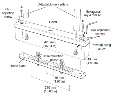
1. Unscrew the roll, pitch and yaw adjusting screws so that they are near the end of their travel.
2. Mount the cover onto the base plate. It is recommended that the ACR1 is supported before screws A and B are fitted.
3. Hand tighten screws A and B until resistance is felt.
4. Use the hexagonal key to tighten down the roll and pitch adjusting screws until resistance is felt. Tighten them down another 3/4 of a turn. The base is now set at the mid position of the adjusting range. Fine adjustment can now be carried out as required.
5. When adjustment is complete, tighten down screws A and B firmly. Maximum torque is 8 N/m (5.9 lbf/ft).
For full adjustment and fitting instructions, please refer to the autochange system user's guide (Renishaw part number H-1000-5090).
Adjustable base - specification
Yaw adjustment range about the nominal centre position | 1 mm (0.039 in) |
|---|---|
Pitch adjustment range nominal limit | 1 mm (0.139 in) |
Roll adjustment range nominal limit | 1 mm (0.039 in) |
Overall base height when assembled | 26 mm (1.02 in) |
Mounting bolts up to 10 mm (0.39 in) diameter can be used.
Cable fitting
To fit a cable to the ACR1, you need to carry out the following procedure:
1. Remove the two M3 x 6 mm securing screws as shown below and remove the cable fixing bracket from the ACR1.
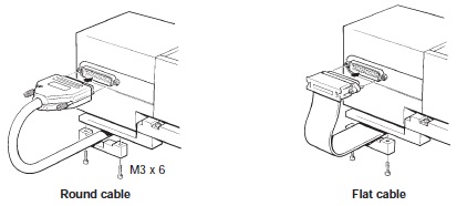
2. Locate the cable into the position where the cable fixing bracket was fitted to the ACR1.
3. Place the cable fixing bracket over the cable into its correct mounting position on the ACR1, ensuring the cable is not pinched.
4. Replace the two M3 × 6mm securing screws into the ACR1.
NOTE: Two different types of cable have been used to connect the ACC2-3 to the ACR1. These cables differ in construction: one is a flat cable, one is a round cable. If it is necessary to replace a flat cable with a round cable, you will probably require a new cable fixing bracket. This is available from your local Renishaw office.
AM1 adjustment module
The AM1 adjustment module is designed to provide quick and accurate angular alignment of either the PH10T PLUS or the PH10M PLUS motorised probe heads with the axes of the CMM and / or the ACR1.
In addition, the quick release mechanism allows the probe head to be removed for storage and replaced without further alignment.
Inbuilt overtravel protection decreases the risk of probe head damage.
AM1 specification
Size | 60 mm × 15.5 mm (nominal) |
|---|---|
Adjustment | ±2 in pitch and roll (recommended) * ±4.5 in yaw |
Overtravel | ±3.5° in pitch and roll |
Mounting | The AM1 mounts to the quill of the CMM via the shank or can be fitted direct to the user's mounting. |
The AM1 is compatible with the MIH, PH6M and most motorised probe heads (i.e. PH10T PLUS and PH10M PLUS).
* Up to 5.5° adjustment is possible in pitch and roll but at the expense of overtravel
AM1 installation
The AM1 installation procedure is as follows:
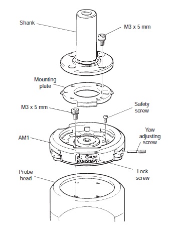
1. Remove the safety screw. Release the lock screw on the front of the AM1. Unscrew fully ONE yaw adjusting screw. Rotate the mounting plate through 60° and remove.
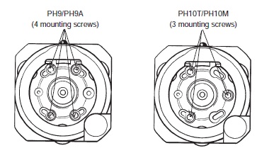
2. Locate the AM1 body to the probe head and secure with 3 × M3 × 5 mm screws.
3. Refit the mounting plate to the AM1 and locate by rotating through 60°.
NOTE: If the shank / mounting plate assembly is to be permanently attached to the head, the retaining screw must be replaced before assembling the shank to the plate. If quick release is required, the retaining screw should not be fitted.
Screw the yaw adjusting screw against the lug.
4. Secure the shank to the mounting plate with the three or four M3 × 5 mm screws provided.
CAUTION: Using longer screws will cause damage to the motorised head.
AM2 adjustment module
The AM2 adjustment module is designed to provide quick and accurate angular alignment of the PH10MQ PLUS motorised probe head with the axes of the CMM and / or the ACR1.
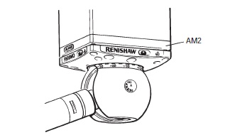
The AM2 provides a highly repeatable mounting, allowing a head to be removed without the need for further adjustment. Because all adjustable parts remain with the head on removal, more than one head can be set up for use on the same machine, the time taken to exchange heads being minimal.
NOTE: The AM2 does not provide overtravel protection.
AM2 installation
The AM2 can be supplied already assembled to the head. Installation requires a 2.5 mm hexagon key and four M3 × 5 mm cap screws to attach the adjuster plate to the quill of the CMM.
1. Unscrew the two securing screws to release the adjuster plate from the head. Attach the plate to the CMM quill using four cap screws, ensuring correct orientation. Tighten screws.
2. Offer the head up to quill and plug in the head and multi-wire cables as appropriate. While ensuring that the balls of the AM2 adjusters engage the seatings in the plate, tighten the securing screws.
NOTE: The springs under the heads of the screws allow a controlled load to be applied.