Navigation
PHC10-3 PLUS system interconnection diagrams
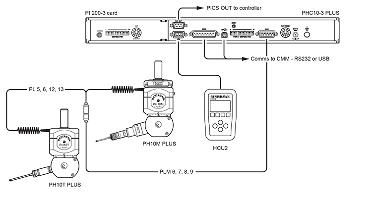
PH10 PLUS system with standard two wire touch-trigger probes
With internal PI 200-3
PH10 PLUS system with standard two wire touch-trigger probes
With internal PI 200-3 and autochange
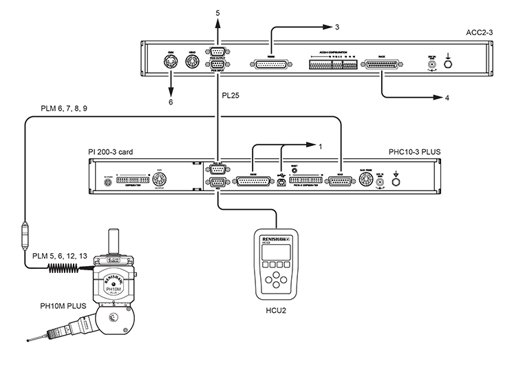
| Key | Description |
|---|---|
| 1 | Communication connection to CMM controller RS232 or USB |
| 3 | Communication to CMM controller |
| 4 | Communication to autochange rack |
| 5 | PICS output to CMM controller |
| 6 | Probe output to CMM controller |
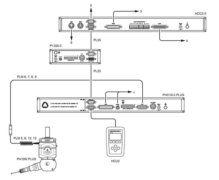
PH10 PLUS system with standard two wire touch-trigger probes
With external PI 200-3 and autochange
| Key | Description |
|---|---|
| 1 | Communication connection to CMM controller - RS232 or USB |
| 3 | Communication to CMM controller |
| 4 | Communication to autochange rack |
| 5 | PICS output to CMM controller |
| 6 | Probe output to CMM controller |
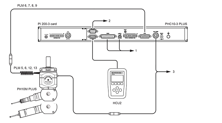
PH10 PLUS system with multiwire scanning probes
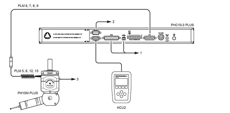
Key | Description |
|---|---|
1 | Comms to CMM controller |
2 | PICS to CMM controller |
3 | Multiwire to probe interface |
PH10 PLUS system with multiwire scanning and touch-trigger probes with internal PI 200-3
Key | Description |
|---|---|
1 | Comms to CMM controller |
2 | Touch-trigger probe and PICS to CMM controller |
3 | Multiwire to probe interface |