Navigation
TP200 product description
Probe body
The TP200 probe body houses the strain sensing structure and electronic processing circuitry.
When the stylus contacts the workpiece, in a normal gauging move, the force applied to the stylus tip is transferred, through the stylus module and the coupling at the front of the probe body, to the silicon strain sensors. A tip deflection of a few μm is sufficient to trigger the probe. The probe's signals are amplified and processed in a hybrid microcircuit electronic assembly. The probe's data and control signals are communicated between the probe and the PI 200-3 interface over a pair of screened wires, allowing the TP200 system to be compatible with the majority of Renishaw probe heads and accessories.
The TP200B probe body uses the same technology as the TP200 probe body but has been designed to have a higher tolerance to vibration. This helps to overcome the problem of 'air' trigger generation which can arise from vibrations transmitted through the CMM or when using long styli with fast positioning speeds.
The stylus module is held in position on the front of the probe body by a magnetic, kinematic coupling. The coupling allows the stylus module to be removed and then replaced such that the stylus tip returns to a highly repeatable spatial position, eliminating the need for requalification.
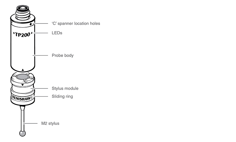
Stylus module
The stylus module carries the M2 stylus mount and provides overtravel in the X, Y and +Z probe axes. Overtravel in the -Z probe axis is accommodated by separation of the module from the probe body.
There are three modules available, with two different overtravel forces:
- The SF (standard force) module is suitable for most applications.
- The LF (low force) module is recommended for use with small precision ball styli or on delicate materials.
- The EO (extended overtravel) module is recommended for use when increasing the speed of the CMM may lead to stopping distances which exceed the overtravel range provided in the SF / LF modules. The EO module has an additional 8 mm of overtravel in the probe Z axis to protect against damage to the probe body in such circumstances. Overtravel force is the same as the SF module.
The module houses the mating half of the magnetically held kinematic coupling (see 'Assembling a stylus on a stylus module'), which ensures repeatable positioning on the probe body. The coupling consists of three bearing points formed by the V grooves on the rear of the stylus module, which seat on three ball bearings located on the front of the probe body. The fourth V groove and semi-recessed ball form an alignment feature to ensure that the module has a unique orientation in the rotational axis. The module and stylus axis will be visibly misaligned if the coupling is not correctly seated.
Alignment symbols are provided to assist manual alignment. The module cover forms a sliding ring (see 'Probe body'), which transfers excess force to the case of the probe body if the maximum Z axis overtravel distance is exceeded.
PI 200-3 interface
The PI 200-3 interface unit powers and services the TP200 / TP200B probe and up to two SCR200 stylus change racks. The PI 200-3 will service kinematic switching probes (TP2, TP20, TP6), in addition to the TP200 / TP200B. The PI 200-3 automatically recognises the probe type, determines the status of the probe and transmits probe trigger signals to the CMM controller.
When automatic stylus changing is performed using the SCR200 change rack, the PI 200-3 inhibits probe triggering and resets the TP200 / TP200B probe to account for the loading effects of the new stylus assembly on the strain sensors. In the event of rack overtravel or error condition, the PI 200-3 transmits signals to the CMM controller to stop CMM motion.
During high speed position moves (fast traverse), it is necessary to reduce probe sensitivity to prevent vibration causing unwanted triggers. The CMM controller automatically switches the PI 200-3 into a low sensitivity mode, such that vibration triggers are prevented. However, a trigger is still issued to stop CMM motion, if an unexpected collision occurs. This mode is known as ‘probe damped mode' and is indicated by an LED on the PI 200-3 front panel.
The CMM manufacturer sets the configuration of the PI 200-3 and it should not be necessary for the user to make adjustments except to operate the reset button, as explained later in this handbook.
SCR200 stylus change rack
The SCR200 holds and protects up to six stylus modules for automatic changing. The modules are magnetically held in the docking ports, which allows the rack to be mounted in any orientation and eliminates the need for high accuracy positioning. No special commands are necessary, as stylus changing requires only simple position moves to be programmed.
The SCR200 incorporates a system of infrared light beams and a Hall effect sensor to detect the presence of the probe and to signal to the PI 200-3 interface that stylus changing is in progress. A self-test mode checks operation of the light beams during power-up.
The rack is provided with an overtravel mechanism to reduce the possibility of damage should a collision occur. When the mechanism is deflected, signals are transmitted to the CMM controller to stop CMM motion. The overtravel mechanism is self-resetting. After a collision, the rack should return to its normal operating position and should not require re-datuming.
