Hydraulic block manifold redesign for additive manufacturing
Additive manufacturing (AM) is highly suited for the design and manufacture of manifolds due to its ability to build internal features and passageways.
Renishaw has collaborated with a customer to redesign their current hydraulic block manifold with AM in mind. The main goal of the project was to reduce the mass of the component whilst retaining its robustness. Due to the increased design freedom associated with AM, an opportunity to increase the efficiency of the flow paths was also identified.
What is a hydraulic block manifold?
A hydraulic block manifold directs the flow of fluid in a hydraulic system linking valves, pumps and actuators. It enables the design engineer to manage the operation of a hydraulic circuit whilst combining the components in a compact unit.
Traditional manufacture of hydraulic block manifolds
Traditionally, hydraulic block manifolds are manufactured from an aluminium alloy or stainless steel billet which has been cut and machined to size, followed by drilling to create the flow pathways. Specialised tooling is often needed due to the complex drilling that is required. Passages require blanking plugs to properly direct flow through the system.
The nature of the manufacturing process results in abrupt angled junctions between flow paths which can cause flow separation and/or stagnation – a major contributor to efficiency loss.
Aluminium alloy manifolds are generally less costly due to lower material costs and ease of machining, however they can be less abrasion resistant, and so any loose particles in the flow will abrade the surface and increase wear. For this reason, stainless steel manifolds are sometimes more desirable, however due to the higher density and hardness of stainless steel compared to aluminium alloy these come with a significant weight increase and added cost of machining.
Benefits of AM for the design and manufacture of hydraulic manifolds:
- Optimised flow paths for a more efficient component functionality
- Ability to fully utilise computational fluid dynamics (CFD) to aid the design process
- Reduction in the requirement for fixturing
- Minimal requirement for removable support structures
- Significant weight reduction is achievable
- No requirement for block extraction passages
- With full design freedom a manifold can be designed to pack into a significantly smaller volume
Direct benefits to customer:
- Mass reduction of up to 79%
- Single piece construction, fewer opportunities for defects
- Rapid design and development iterations
- Compatibility with existing design
- Improved flow efficiency of up to 60%
Redesign for AM - Design scope
AM allows a higher level of design freedom, so the component geometry could be adapted to reduce material mass and improved functionality, within the same space. Renishaw was given certain design and function guidelines by the customer which had to be considered when redesigning the component:
Geometry
- Defined connection ports
- Inner diameters of flow passages
- Wall thicknesses of the flow passages
- Fixture points and interfaces
Function
The customer's main requirement was weight reduction, whilst still maintaining its rigidity and functionality. Renishaw design engineers also recognised scope in the redesign for AM to improve the efficiency of the flow paths within the system.
First design iteration
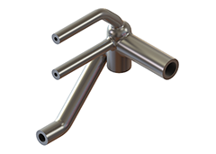
The first step was to de-construct the part into just the essential passageways that provide the functionality of the hydraulic block manifold. The flow paths of the original cross-drilled design were extracted using CAD software, and any drilled areas that are not required for the flow path were removed, leaving the essential pipe network.
Each hydraulic circuit was then reduced and simplified in preparation for piece-wise computational fluid dynamics (CFD) analysis, using SOLIDWORKS Flow Simulation.
Next, the flow paths were optimised after identifying areas of flow separation and stagnation gained via CFD analysis.
Wall thickness was then generated, in this case based on the customer specification, but alternatively this could be done by using finite element analysis (FEA) stress modelling based on pressure readings taken during CFD analysis.
Finally, permanent support structures were designed and added in to the CAD geometry, creating a self-supporting, efficient structure. Generally, support structures are added to a final geometry in post processing of the component design in order to anchor the object to the baseplate and dissipate heat – however making the supports part of the component design reduces the potential waste material associated with removable support structures or anchors.
The first design iteration resulted in a reduction in volume of 52% compared to the original block manifold, as well as an improvement in flow efficiency of up to 60%.
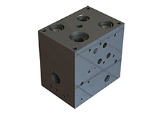
Original block manifold. Flow passages are cross drilled and plugged to direct flow.
First iteration geometry. Flow paths have been extracted, optimised and wall thicknesses applied. Support structures act to hold the flow paths in place and connect fixture points.
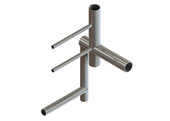
Extracted flow path section highlighting abrupt junctions.
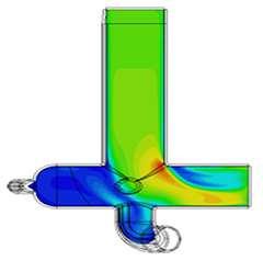
CFD analysis example highlighting areas of disturbed flow.
Flow path section generated after CFD analysis; severity of corner angles have been reduced for optimised flow.
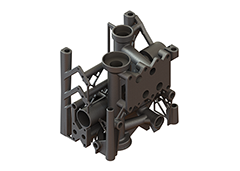
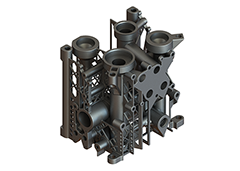
Second iteration geometry. The block extraction passages have been removed and the support structures reworked for increased stiffness and rigidity.
Second design iteration
The first iteration was built at Renishaw and evaluated by the customer who assessed the new geometry in the context of its function as a hydraulic manifold; the original manifold is designed to be used modularly, with multiple units installed in series. Individual hydraulic block manifolds will occasionally need to be extracted from the line up for servicing; making it necessary to include threaded ‘block extraction' passages.
The first iteration for AM geometry has features that an engineer can use to extract the manifold manually without the use of tools, negating the requirement for the block extraction passages. While the removal of these block extraction passages from the CAD model immediately disrupted the intricate network of self-supporting structures, this was seen as an opportunity to re-develop the design.
It had been suggested that iteration 1 might be subjected to flexure, torsional distortion and/or chatter during machining due to the now reduced volume of material relative to a solid block. While simultaneously increasing its stiffness, the redesign resulted in a final manifold which was just 21% of the volume of the original.
This significant reduction in volume now opened up the option of producing iteration 2 in the more desirable stainless steel 316L. This resulted in a net reduction in weight of 37% even in a material with higher density (8 g/cm3 for stainless steel and < 3 g/cm3 for aluminium alloy)
Results summary
| Design stage | Material | Volume (cm3) | Mass (kg) |
| Original hydraulic manifold | Aluminium alloy | 9600 | 25.6 |
| Design for AM 1st iteration | Aluminium alloy | 4650 (-52%) | 12.3 |
| Design for AM 2nd iteration | 316L stainless steel | 2040 (-79%) | 16.3 |
Working with Renishaw
At Renishaw we understand that in order to get the best possible components from an additive manufacturing process, the user needs to understand that designing for AM has a higher level of freedom compared to traditional manufacturing techniques such as subtractive machining and casting. We provide training and design for process support even after the purchase of an AM system.
Renishaw Solutions Centres provide secure development environments in which customers can expand their knowledge and confidence using AM technology. They will be equipped with the latest AM systems and staffed by knowledgeable engineers to allow fast access to deploying the technology, all at fixed predictable costs.
Find out more
To find out how our AM Solutions Centres can benefit you, contact your local Renishaw office.