Navigation
System interconnection diagram
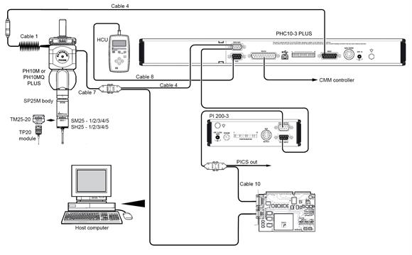
A typical interconnection diagram using the AC3 analogue interface card is shown below. For more detail, please refer to the SP25M installation and integration guide (part number: H-1000-7541) which can be downloaded in PDF format from the Renishaw website www.renishaw.com/cmmguides.
CAUTION: Ensure that the appropriate switch settings are selected on the AC3 card. These settings can be found on the AC3 analogue interface PC card installation webpage.
The SP25M probe connects to the AC3 card through the probe head and through a standard Renishaw multiwire cable. This cable connects directly to the probe head via a micro-D and terminates in a 15-way high-density D which connects directly to the rear panel of the AC3.