How do interferometric systems work?
How does interferometry work?
Introduction
The most common tool in interferometry, the Michelson Interferometer was invented by Albert Abraham Michelson in 1887, the first American to win a Nobel Prize for science. He came up with a system of mirrors and semi-transparent mirrors (beam splitters) for merging separated beams of light, which are coming from the same source. Laser interferometry is a well-established method for measuring distances with great accuracy.
Basic principles
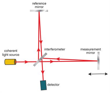
Typically a single incoming beam of coherent light source will be split into two identical beams by a Michelson interferometer. Each of these beams travels a different route, called a path, and they are recombined before arriving at a detector. The difference in the distance travelled by each beam creates a phase difference between them. It is this introduced phase difference that creates the interference pattern between the initially identical waves, which is identified on the detector. If a single beam has been split along two paths (measurement and reference), then the phase difference is diagnostic of anything that changes the phase along these paths. This could be a physical change in the path length itself or a change in the refractive index through which the beam travels.
Michelson interferometry
The laser beam (1) emerges from the laser source and gets split into two beams (reference (2) and measurement (3)) at the interferometer. These beams get reflected back from the two retroreflectors, recombine at the interferometer before reaching the detector.

The use of retroreflectors ensures that the beams coming from the reference and measurement arms are parallel when they recombine with each other at the interferometer. The recombined beam (4) reaches the detector where they interfere with each other either constructively or destructively. During the constructive interference the two beams are in phase and the peaks of both beams reinforce each other resulting in a bright fringe, whereas during the destructive interference the beams are out of phase and the peaks of one beam are cancelled by the troughs of the second beam resulting in a dark fringe.
Signal processing
The optical signal processing in the detector allows the interference of these two beams to be observed. The displacement of the measurement beam causes change in the relative phase of the two beams. This cycle of destructive and constructive interference causes the intensity of the recombined light to undergo cyclic variation. One cycle of variation in intensity from light to dark to light occurs every time the measurement beam/retroreflector (3) is moved by half the laser wavelength.
Accuracy of the system
The accuracy of the linear positional measurements depends on the accuracy to which the wavelength of the laser beam is known. The operational wavelength of the laser beam depends on the frequency of the laser and the refractive index of the air through which it passes. This refractive index changes with any variations in air temperature, air pressure, and relative humidity.
RLE laser encoder systems
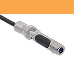
The RLE system is a unique, advanced homodyne laser interferometer system specifically designed for position feedback applications. Each RLE system consists of an RLU laser unit and one or two detector heads, the model of which is dependent upon the requirements of the specific application.
Key:
 |  |  |

What is in an RLE laser encoder system?
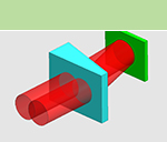
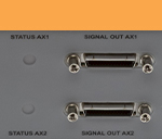
| Laser source | Fibre coupling | Interferometer optics | Measurement optics | Detection scheme | Encoder feedback signals |
 |  |  |  |  |  |
What does the RLU laser unit do?
Outputs laser light to detector head
| Laser source | Stabilisation electronics | Fibre coupling | Beam pointing stability |
Frequency stabilised Class 2 HeNe laser |  | Utilising Renishaw's unique fibre optic delivery system | 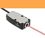 Key to ensuring a stable beam position on the measurement optics over extended periods of time |
Processes analogue quadrature signals from the detector head
| Error signals and diagnostics | System status | Digital interpolation | Analogue encoder signals |
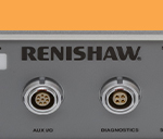 Error lines report encoder status to the machine control system for robust closed loop operation. Additional information is available through a diagnostic interface. | 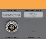 LED interface located on the front of the RLU to provide intuitive indication of operational status |  | 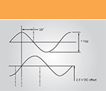 |
What does the detector head do?
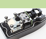
Delivers laser beam to measurement optics
| Interferometer optics | Beam steerer |
Unique optical schemes with minimised SDE compatible with plane mirror measurement optics | 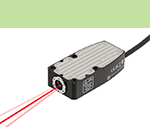 An in-built optical wedge used to minimise the installation time by providing simplified angular beam adjustment |
Generates analogue quadrature signals from measurement beam and reference beam
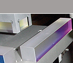
| Analogue encoder signals | Detection scheme | Measurement optics |
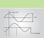 Intrinsic analogue quadrature generated from the detection scheme and passed directly to the RLU laser unit | In-built fringe detection scheme converts the interference fringes from the measurement and reference beams into an electronic signal | Highly reflective hard oxide coated dielectric mirrors |
Explore our why use a laser encoder article to gain a better understanding of how our products can improve your processes.
Discover our range of interferometric laser encoders designed to meet your high-accuracy motion control needs.
Contact our sales team today
Get in contact with your local office to find out more information and speak to an expert.