Interferometry explained
Laser interferometry is a well established method for measuring distances with great accuracy.
What is interferometry?
'Interferometry' is a measurement method using the phenomenon of interference of waves (usually light, radio or sound waves). The measurements may include those of certain characteristics of the waves themselves and the materials that the waves interact with. In addition, interferometry is used to describe the techniques that use light waves for the study of changes in displacement. This displacement measuring interferometry is extensively used for calibration and mechanical stage motion control in precision machining.
By using two light beams (usually by splitting one beam into two), an interference pattern can be formed when these two beams superpose. Because the wavelength of the visible light is very short, small changes in the differences in the optical paths (distance travelled) between the two beams can be detected (as these differences will produce noticeable changes in the interference pattern). Hence, the optical interferometry has been a valuable measurement technique for more than a hundred years. Its accuracy has later been improved with the invention of lasers.
The first demonstration of using light interference principles as a measurement tool was achieved by Albert A. Michelson in the 1880's by developing the first interferometer. Although the technology (and the measurement accuracy) has been developed over the years since, the basic underlying principles of the Michelson interferometer still remains at the core of interferometry.
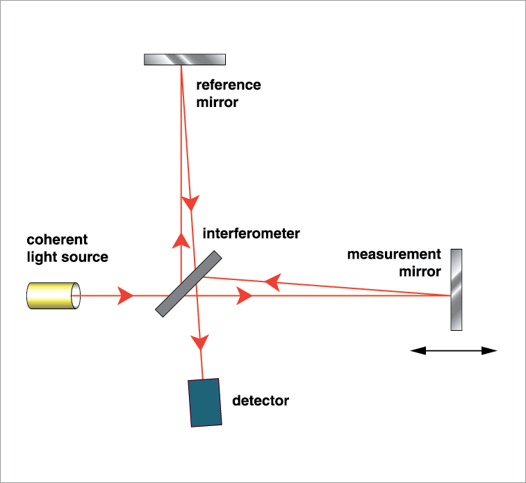
A Michelson interferometer consists of a beamsplitter (half-silvered mirror) and two mirrors. When the light goes through the half-silvered mirror/beam splitter (which is partially reflecting) it is split into two beams with different optical paths (one going to mirror 1 and the other going to mirror 2). After being reflected back at the mirrors these beams recombine again at the beam splitter before arriving at the detector. The path difference of these two beams causes a phase difference which creates an interference fringe pattern. This pattern is then analysed by the detector to evaluate the wave characteristics, material properties or the displacement of one of the mirrors (depending what measurement the interferometer was being used for).
How does an interferometer work?
In order to generate an interference pattern with high precision (distinct fringes), it is very important to have a single highly stable wavelength source, which is achieved using the XL-80 laser interferometer.
There are different interferometer set up's based on Michelson's principle, however, the linear set up is the simplest type to explain.
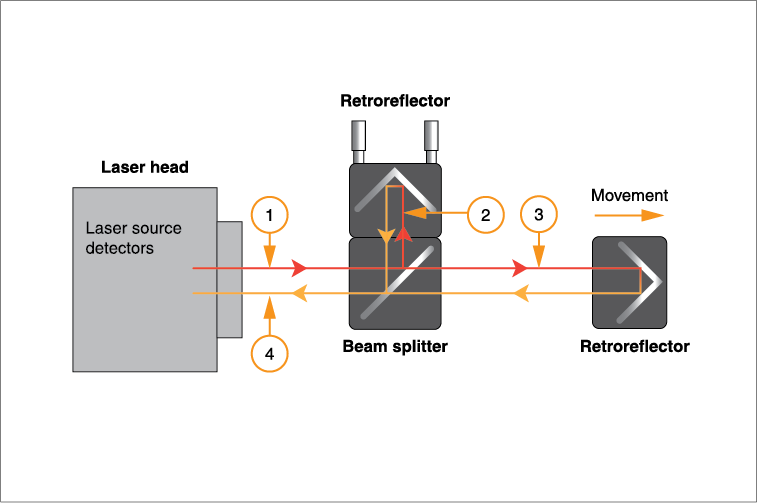
In the XL-80 laser system the two mirrors (used in the Michelson interferometer) are retroreflectors (prisms that reflect the incident light back in the direction parallel to the direction from which it came from). One of these is attached to the beam splitter forming the reference arm. The other retroreflector forms the variable length measurement arm as its distance varies in respect to the beam splitter.
The laser beam (1) emerges from the XL-80 laser head and gets split into two beams (reflected (2) and transmitted (3)) at the polarising beam splitter. These beams get reflected back from the two retroreflectors, recombine at the beam splitter before reaching the detector. The use of retroreflectors ensures that the beams coming from the reference and measurement arms are parallel when they recombine with each other at the beam splitter. The recombined beam reaches the detector where they interfere with each other either constructively or destructively. During the constructive interference the two beams are in phase and the peaks of both beams reinforce each other resulting in a bright fringe, whereas during the destructive interference the beams are out of phase and the peaks of one beam are cancelled by the troughs of the second beam resulting in a dark fringe.
The optical signal processing in the detector allows the interference of these two beams to be observed. The displacement of the measurement arm causes change in the relative phase of the two beams. This cycle of the destructive and constructive interference causes the intensity of the recombined light to undergo cyclic variation. One cycle of variation in intensity from light to dark to light occurs every time the measurement arm/retroreflector is moved by 316.5 nm, which is half the laser wavelength (as this movement causes the optical path to change by 633 nm, which is the laser wavelength). Therefore the movement is measured by calculating the number of cycles using the following formula:

Where d is the displacement (in microns), λ is the wavelength of the laser (0.633 microns), and N is the number of fringes passed. The higher resolution of 1 nm is achieved by phase interpolation within these cycles.
No matter how good your laser unit is (i.e. how accurate and 'stable' it is) the accuracy of the linear positional measurements depend on the accuracy to which the wavelength of the laser beam is known. The operational wavelength of the laser beam depends on the refractive index of the air through which it passes and this alters with air temperature, air pressure and relative humidity. Therefore, the wavelength of the beam needs to be altered (compensated) to incorporate any changes in these parameters.
Applying environmental compensation
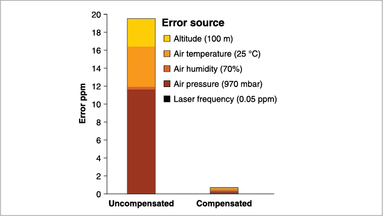
Without reliable and accurate wavelength compensation, errors of 20 ppm - 30 ppm would be common in linear measurement readings when variations of temperature, humidity and pressure for nominal values are combined (even if the test conditions remain stable). These errors can be reduced by an environmental compensator unit (XC-80 compensator) ensuring that XL-80 measurements maintain accuracy over a wide range of conditions. The following graph on the right provides an example of the error in an uncompensated interferometry system and the source of these errors.
The XC-80 measures the air temperature, pressure and humidity, then calculates the refractive index of air (and hence the wavelength of the laser). The laser read-out is then automatically adjusted to compensate for any variations in the lasers wavelength. The advantage of an automatic system is that no user intervention is required and that compensation is updated frequently.
Note: Environmental compensation is NOT required for angular or straightness measurements when using a Renishaw laser system. This is because the measurement is calculated from the differences in the two beam paths that are close, and so the environmental effects self cancel. As rotary axis, flatness and squareness measurements are also based on these measurements, they also do not require environmental compensation.
Remote interferometry
Some systems locate the interferometer/beam splitter within the laser head. Thermal growth of the laser head changes the measurement path length, so additional warm-up time is needed before accurate measurements can be taken. By using a remote beam splitter, Renishaw avoids this problem.Find out more
Browse our range of machine calibration and optimisation products designed to improve the performance of precision motion systems.
And find out more about interferometric laser encoders provide the ultimate accuracy in linear position feedback.


Contact our sales team today
Get in contact with your local office to find out more information and speak to an expert.