Introduction to multi-DoF encoders
A multi-DoF (multiple degrees of freedom) encoder reading a single scale can measure any combination of X (primary linear axis), Y (secondary linear axis), and Rz (secondary in-plane rotation axis, also known as yaw), as shown in Figure 1. Combining multiple scales in different orientations enables all six degrees of freedom (6DoF) to be measured. Typically, the ranges of motion for the secondary axes are small.
Multi-DoF encoders use special scales with two sets of scale lines, typically arranged at 90° from each other. The line pattern can vary between different multi-DoF encoder systems.
Additional readheads or sensors collect data from the secondary axes. At least one additional sensor or readhead is required for each additional degree of freedom.
In many cases, the secondary degrees of freedom will not require the same metrology performance as the primary one. For example, the secondary axes are likely to experience lower velocities, as they only have short travel distances, and may not be moved deliberately. Also, the secondary axes may only impact the target positions of the primary axis rather than directly feeding into the primary axis control loop.
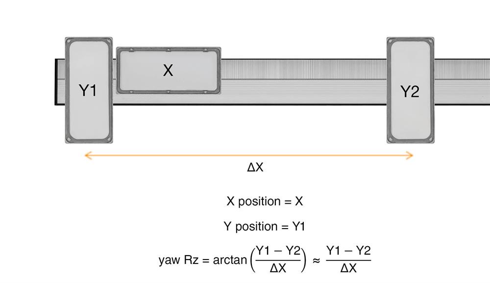
Figure 1: A multi-DoF encoder being used to measure X, Y and Rz.
Why are multi-DoF encoders useful?
Multi-DoF encoders can be used in two main ways which are not possible with conventional encoders.
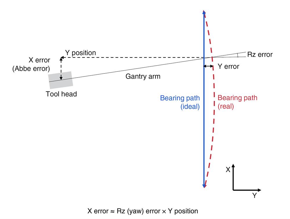
Figure 2: X (Abbe) error and Y error in a gantry system due to an out-of-straight bearing. A multi-DoF encoder can enable accurate correction of these errors.
First, they can measure small movements in secondary directions and correct for the primary axis errors caused by these movements. Due to the direct feedback achieved with multi-DoF encoders, this compensation can be effective for both repeatable and non-repeatable motion. As seen in Figure 2, even moderate distortion of the primary axis can result in significant error at the point of interest. Multi-DoF encoders can correct for these errors.
The second important use case for multi-DoF encoders is to enable deliberate, short stroke movement in additional axes. This can be achieved within a very compact encoder arrangement. This may be particularly valuable to achieve precise positioning close to the point of interest, where wider machine distortions have lessened impact.
Multi-DoF encoders are also designed to permit motion in a secondary linear degree of freedom. They are therefore typically able to accommodate more motion in these axes than would be possible for conventional 1D encoders.
What are the key types of multi-DoF encoder?
Multi-DoF encoders generally have two linear scale patterns which are orthogonal to each other. There are two common types of multiDoF scale: Pure X and Y, and herringbone, as shown in Figure 3. Herringbone scale is sometimes called chevron scale or diagonal scale. Pure X and Y systems have a separate scale pattern for each linear degree of freedom (e.g. X and Y). A herringbone scale also has two orthogonal patterns, but each pattern contributes position data in both the X and Y directions. Neither scale can provide X or Y position on its own. This herringbone structure requires both sensors to be of the same type and to communicate synchronously.
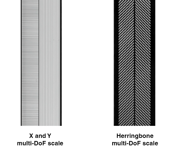
Figure 3: Two common line patterns for multi-DoF scales.
Advantages of pure X and Y scales over herringbone scales
Easier to extract and use linear position using pure X and Y systems
Pure X and Y systems have scales directly aligned with the two linear degrees of freedom, so no calculations are required to obtain X and Y linear positions. By contrast, herringbone systems require information from both sensors to be combined to generate position for each linear degree of freedom. This processing must be well synchronised to avoid unintended errors.
Having an easy-to-extract X position simplifies the process of switching from a standard linear encoder design to a multi-DoF arrangement. Most multi-DoF applications still have the majority of their motion on a single axis. A pure encoder output on that primary axis reduces the amount of redesign needed to support system functions using that axis, such as position, velocity and acceleration control loops, triggering systems, and error mapping. The secondary Y and Rz axes can be used to enhance the performance of the primary axis when required.
Easier to extract Rz with pure X and Y systems
Evaluating Rz rotary movement is straightforward with pure X and Y encoder systems: position information from just two Y sensors is combined with some simple geometric information. By contrast, with herringbone systems no single sensor can give local Y position and so 4 position signals must be combined to be able to extract Rz information.
X and Y systems allow greater flexibility in sensor positioning
Herringbone systems require both sensors from an XY pair to be close to each other to prevent relative motion, such as that caused by thermal expansion or rotation about Rz. Such motion will produce position errors in both dimensions.
However, with pure X and Y encoders there are no constraints on the positioning of the sensors relative to each other because they act independently of each other. It is even possible to have a highly compact system which only measures Y and Rz, if required. This flexibility can provide extra design freedom when operating in space-constrained machines, and may allow sensors to be mounted closer to the point of interest. A selection of readhead arrangements is shown in Figure 4.
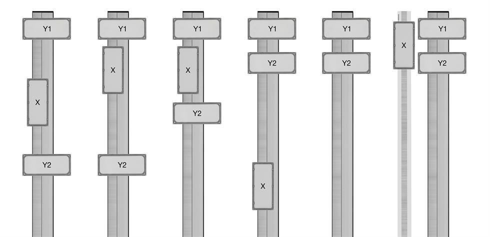 Figure 4: A range of readhead placement options available with X and Y encoder systems.
X and Y encoders can be less vulnerable to thermal distortion
X and Y encoders require only three sensors to measure X, Y and Rz. As Y position information is extracted from encoder signals which are not affected by X position, Y and Rz measurements are substantially immune to X expansion of either the scale or the mounting brackets.
Herringbone systems can measure Rz using only three sensors, but this is prone to significant errors. A pair of adjacent sensors must be used to calculate X and Y1 and a third sensor at a different X position is used to measure Y2. However, as this third sensor cannot directly measure Y position, it must employ an X position derived from the other pair of sensors, as show in Figure 5.
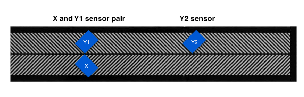
Figure 5: A sensor arrangement to measure X, Y and Rz using only three sensors with a herringbone 1.5D scale.
When using this three readhead arrangement, any change in the X separation between the two sets of encoders will produce errors in Rz. This X separation may vary due to thermally or mechanically induced expansion of either the scale or the readhead mountings.
An expansion of the gap between the pairs of sensors will produce an error in the assumed X position of the second Y sensor, leading to error in Y2 and consequently error in Rz.
Therefore, with a herringbone encoder system, it is only possible to accurately calculate Rz with four sensors mounted in two pairs.
Different scale types can be used on each axis
Pure X and Y multi-DoF encoders measure the two linear degrees of freedom independently, so it is possible to use a different scale/ encoder type on each. Herringbone encoders require interaction between the linear scales, so they must be of the same type. An example of a mixed-type multi-DoF encoder would be a system that features an incremental long primary axis and an absolute short secondary axis. This arrangement removes any need for homing the short axis while maintaining all the benefits of incremental encoders for the long axis.
What are some potential weaknesses of X and Y multi-DoF encoders?
It can be difficult for pure X and Y incremental encoders to reference their Y position, because there may not be a mechanism to move the Y encoder past a homing point. This is not an issue if the Y axis is absolute.
Herringbone systems only require sufficient X motion travel to ensure all their readheads can pass over their reference marks. Examples of reference marks for pure X and Y systems and herringbone encoders are shown in Figure 6.
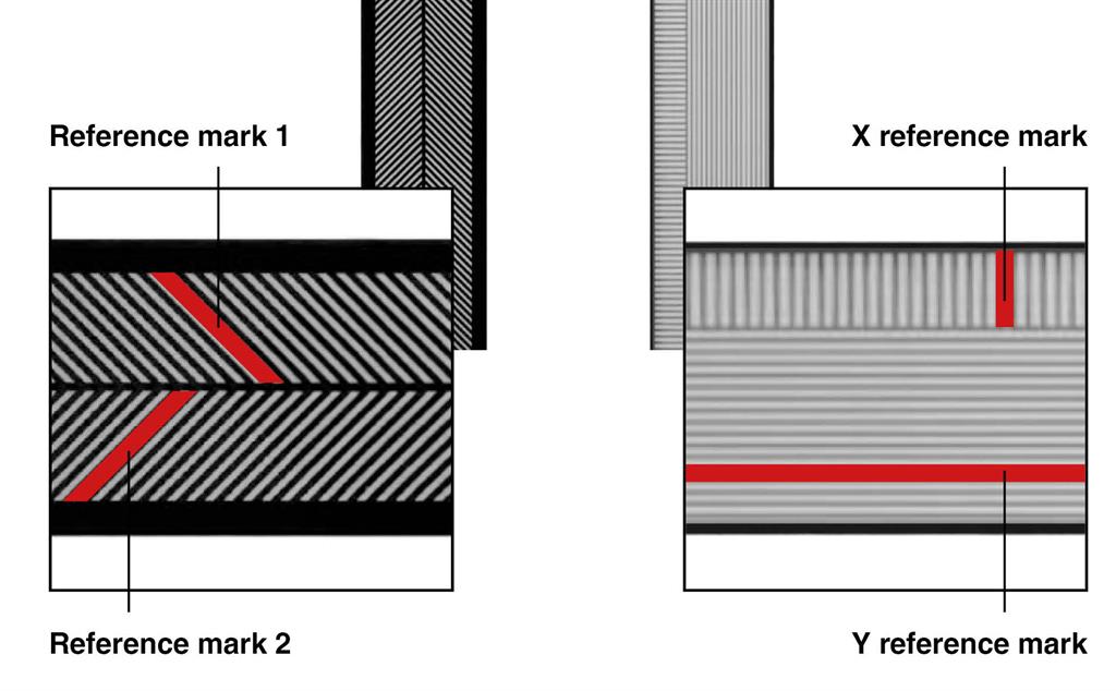
Figure 6: Reference mark arrangements for incremental multi-DoF scale systems.
Applications where multi-DoF encoders may be useful
Multi-DoF encoders are useful in many applications where exceptional metrology is required. Below are a few examples when multi-DoF encoders may be valuable.
Advanced Packaging
Advanced Packaging (AP) is a challenging motion control application where components must be very accurately placed in X, Y and Rz. The effect on placement accuracy of a small rotational error is shown in Figure 7. To achieve acceptable throughputs, a high rate of component placement is required so packaging systems require fast, dynamic motion.
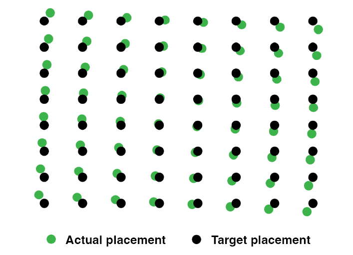
Figure 7: Slight rotational errors lead to significant bond placement errors on large dies.
Multi-DoF encoders can help to achieve accurate component placement. They provide high-accuracy position feedback in all key degrees of freedom. Additionally, due to the compact readhead arrangements possible, the position sensors used for any final position adjustments can be placed close to the point of interest, improving placement accuracy.
Multi-DoF encoders can also improve the dynamic behaviour of AP machines. They provide compact 3DoF measurement which can be fitted within the bondhead, enabling fine positioning using short stroke, dynamic axes. This can improve dynamic performance compared to moving the whole bondhead/gantry using the long stroke gantry axes.
Position adjustment within the bondhead also reduces vibrational crosstalk between multiple bondheads on the same machine. Compared to moving the whole bondhead/gantry, smaller masses and forces are used, generating less vibration and mechanical distortion. This helps to improve isolation between different bondheads operating on the same machine.
Correcting for axis distortion
Using multi-DoF encoders can improve the performance of multi-axis machines. These encoders enable the measurement and correction of movement perpendicular to the intended motion for each axis. Corrective action may include driving other axes to compensate for this motion, or to provide a warning that machine servicing may be required.
Multi-DoF encoders can even improve the performance of machines which have had multi-DoF error maps created, as these error maps cannot correct for all types of off-axis movement. There are two weaknesses of error maps. First, as the machine and bearings wear and change, error maps may become less accurate. Second, error maps cannot correct for errors which develop or change during operation of the machine. These are likely to result from thermal distortions and mechanical effects, such as changing loading conditions or operation in dynamic conditions, as shown in Figure 8. Multi-DoF encoders can measure off-axis imperfections which are generated after error mapping, enabling better machine performance.
Controlling dynamic distortions can be important for a wide range of precision motion control systems, including precision XY stages, gantry systems and optical inspection systems.
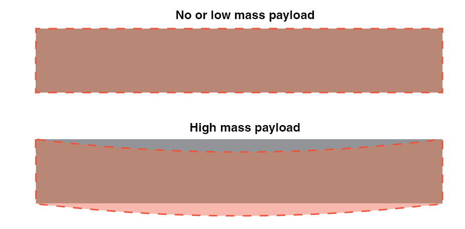
Figure 8: A gantry during calibration with no or low mass payload (grey) and while moving a high mass payload (red). The gantry is slightly distorted by this variable load, degrading the accuracy of any previous error mapping processes. A carefully configured multi-DoF encoder can detect these changes in real time.
Renishaw multi-DoF products
Renishaw's multi-DoF encoder systems use a pure X and Y scale arrangement, typically being sensed by the high-performance RESOLUTE™ encoder readheads for both axes, although alternative encoders are possible if required. Low-stiffness self-adhesive tape is recommended for mounting to isolate the scale from any distortion of the axis, enabling this distortion to be measured. Contact your local sales representative for more information.
Contact our sales team today
Get in contact with your local office to find out more information and speak to an expert.