Magnetic encoders support the stabilisation control of a self-balancing two-wheeled robotic vehicle
In the design of a self-balancing two-wheeled robotic vehicle, accurate high-speed measurement of angular rotation is a key requirement. Furthermore, the minimisation of component weight and size is an equally vital consideration. Engineering students at Tokyo Denki University found the answer in the RM08 rotary magnetic encoder, from Renishaw's associate company, RLS.
Background
Dedicated to the teaching of science and technology, Tokyo Denki University was established in 1907 by two young engineers, Seiichi Hirota and Shinkichi Ogimoto. Their founding principle was to promote engineering education as a basis for national economic development.
Working in the University's Robotics and Mechatronics Department, Jun Ishikawa is a pioneering researcher in several technological fields including robot control system development. He challenged his engineering students to create a two-wheeled, self-balancing robotic vehicle. For this project, his students chose the RM08 rotary magnetic position feedback encoder from RLS, a Renishaw associate company.
 The RM08 is a miniature high-speed rotary magnetic encoder
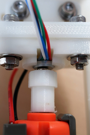
The encoder coupled to the motor shaft
Challenge
Ishikawa challenged his university students to solve a classic control theory problem - the inverted pendulum. The basis for the well-known Segway personal transporter, the inverted pendulum has its centre of mass located above the pivot point.
Unlike a suspended pendulum, which will naturally return to a stable equilibrium position after being displaced, the inverted pendulum is inherently unstable. Imagine holding a pool cue or a broom handle upright on the palm of your hand - it would tend to fall over without continuous adjustments to the position of your hand.
A shorter inverted pendulum accelerates away from the vertical position faster than a longer one, requiring more frequent position adjustments and presenting a more challenging control problem – balancing a pen on your hand is trickier than balancing a pool cue.
One solution to the problem, as implemented by Segway, is to mount the pivot point on a wheeled platform. This type of vehicle takes inertial inputs from an IMU (inertial measurement unit) which comprises two sensors: an accelerometer and a gyroscope.
In this case, both vertical-axis and horizontal-axis accelerometers are used to determine the angular acceleration due to gravity. By constantly monitoring the tilt angle and angular velocity of the pendulum, a PD (proportional-derivative) control system can be used to drive the wheels forwards or backwards to maintain balance.
Adopting a similar approach in their own control system, Ishikawa's students needed to design and integrate what was effectively a three-part solution, comprising tilt-angle sensing, control logic and motor drive circuitry. When designing PCBs for this control application, small size and low weight is crucial for integration within the handlebars. PCB architectures have been optimised to ensure that all the required functionality is delivered in the smallest package size.
Solution
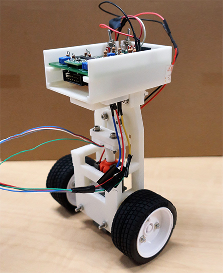
The PCB control board sits at the top of the pendulum, inside the handlebars, and carries all the electronic circuitry required, including a solid-state gyroscope, microcontroller, DC motor drive and power management components.
In the wheeled platform, at the bottom, there are two axles: a horizontal axle linking the wheels and a vertical axle driven by a compact DC motor. Simple bevel gearing at the intersection between the axles enables the motor to drive the wheels in either direction.
For effective control, the system must maintain orientation within a small range of angles that are nearly vertical. If the vehicle tilts by more than 30 degrees in either direction, stability might be lost. To maintain balance, the wheels must be driven continuously with carefully calculated acceleration and speed.
To achieve the required level of motion control performance, the students needed a high-resolution position encoder to enable monitoring and regulation of the motor output. It also had to be small and light enough to be accommodated within the vehicle's slim vertical structure.
After much consideration, the solution came in the shape of the RM08 rotary magnetic encoder from RLS, a Renishaw associate company. This non-contact, frictionless rotary magnetic encoder weighs just 2 g, including cabling, and features an aluminium sensor housing measuring 8 mm in diameter with a thickness of only 3 mm.
The students designed a narrow nylon collar, to act as a mechanical linkage between the motor shaft and the magnetic actuator of the RM08 encoder, which added less than 0.5 g to the assembly. The RM08 encoder produces a 12-bit resolution output (4,096 steps per revolution), is suitable for high-speed operation up to 30,000 rpm and delivers an accuracy of ±0.3 º.
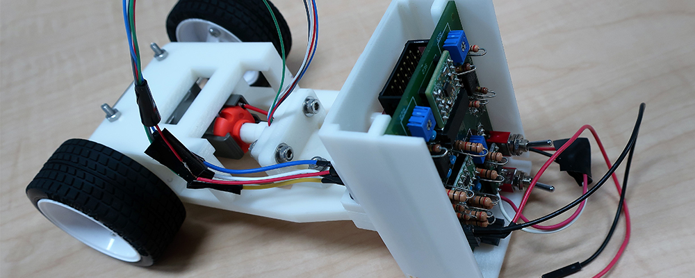
The two-wheeled, self-balancing robotic vehicle designed by the engineering students at Tokyo Denki University
Results
By using the RM08 high-speed rotary magnetic encoder to measure angular rotation at 12-bit resolution, the Tokyo Denki University students were able to design a motion control scheme for a two-wheeled robotic vehicle capable of self-balancing and staying upright.
The RM08 encoder is IP68-rated and designed for integration into a wide range of high-reliability, high-volume OEM applications.
Importantly, the rotary magnetic encoder also addressed the vehicle's demanding physical design constraints. Being a highly compact and lightweight component, it helped the students overcome both space and load-carrying limitations.
The success of this project has given the students the confidence to explore other advanced robotics projects.