Navigation
Establishing SCP80(V) port datums
The following section describes the recommended procedure for datuming each installed SCP80(V) port. Before commencing the following should have been completed:
- The SCP80(V) ports should have previously been fitted to the MRS rail (or extrusion) and aligned to the CMM axes
- The SP80 / SP80H probe should have been correctly installed, aligned and fitted with a suitable M5 stylus
- The probe and stylus should have been calibrated and made ready to take single point measurements
Procedure for establishing the port datum for SCP80 and SCP80V
Both rack port types use the same procedure just in different orientations. The following routine should be completed using manual CMM control.
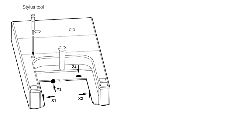
1. Open the port lid to the extreme of travel and place a stylus tightening tool or similar object into the retaining hole to keep it in place.
2. Take 4 points on the jaw plate as follows:
- Take points 1 and 2 across the central jaw and record X1 and X2 values
- Take point 3 at the rear edge and record the Y3 value
- Take point 4 on the top face of the jaw plate (take care not to hit the post on the rack lid) and record the Z4 value
3. Create the X and Y port datums as follows:
- X origin = (X1 + X2)/2
- Y origin = Y3 – 41.5 mm + (stylus tip diameter/2)*
- Store the datums then assign them, and the port, an identification number
4. Create the Z port datum using one of the following methods:
The Z origin must be created in a way that enables satisfactory changing of the SH80 in the SCP80 over the entire stylus range (mass) that the SP80 can carry. This range is from 33 g to 500 g with the effect that ‘droop' increases with mass.
METHOD 1 (preferred)
This method will ensure the SH80 enters the docking slot of SCP80 such that the docking features are centrally aligned in the Z axis.
- Using the port calibration stylus supplied with the probe kit, the probe should be nulled. A temporary Z port datum should be calculated as follows:
Temporary Z origin = Z4 – (stylus length + (stylus tip diam/2)* + 38 mm) - Then for all other stylus configurations, with differing mass, the Z port datum should be calculated as follows:
Z origin = Z4 – (stylus length + (stylus tip diam/2)* + 38 mm – ZOFFSET)
(Where ZOFFSET is the value of any Z axis droop observed with heavier styli mass). - Store the datum then assign it, and the port, an identification number.
METHOD 2 (non-preferred)
This method is simpler to use and merely uses a constant ZOFFSET value which will allow any stylus configuration within the SP80 carrying range of 33 g to 500 g to be docked.
However, the user will notice the following characteristics during docking when using this method: with lighter styli the SH80 will be seen to pull downward, and with heavier styli the SH80 will be seen to pull upward.
- Using the port calibration stylus supplied with the probe kit, the Z port datum should be calculated as follows:
Z origin = Z4 – (stylus length + (stylus tip diam/2)* + 37 mm)
- Store the datum and assign it, and the port, an identification number
* Assuming no tip compensation when measuring.