Navigation
SP80 specification
SP80 probe system
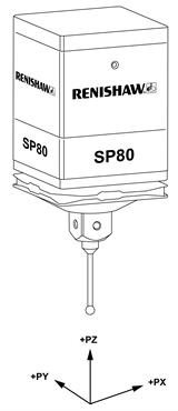
The probe orientation shown below is the orientation used in the SP80 probe product specification.

| Probe attributes | Ultra-high accuracy scanning probe with three axis measurement (±PX, ±PY, ±PZ)* |
| Orientation | Vertical |
| Size | 80 mm × 80 mm (3.15 in × 3.15 in) body, 150 mm (5.91 in) long including SH80 stylus holder |
| Quill mounting | KM80 - 80 mm × 80 mm quill to kinematic SP80 quill mount (standard) KM6080 - 60 mm × 60 mm quill to 80 mm × 80 mm kinematic SP80 probe mount (option) SM80 - shank mount and other custom made adaptor plates available - contact your Renishaw supplier for details |
| Measurement range | 3-axis measurement: ±2.5 mm (±0.12 in) (PX, PY, PZ)* |
| Overtravel range | PX* and PY* protected by breakout of the kinematic joint to the SH80 PZ* has a mechanical 'bump-stop' |
| Resolution of digital scales | 0.02 μm |
| Measurement capability test to ISO10360-2** | Typically <1.0 μm with a 50 mm stylus |
| Scanning capability test to ISO10360-4** | Typically <1.5 μm MPETHN with a 50 mm stylus Time for typical scan = 74 s |
| Return to zero | Approximately 1% of working deflection |
| Spring rate | Approximately 1.8 N/mm (X, Y, Z) |
| Stylus carrying capability | Renishaw M5 stylus range Maximum 500 g mass (unbalanced) Maximum 1000 mm projection # |
| Mass | SP80 probe body only: 860 g SH80 stylus holder: 185 g KM80 quill mount: 110 g |
| Pull off force of SH80 | <20 N when using SCP80 - otherwise approximately 80 N |
| Probe power supply | +9 V to +18 V @ 300 mA maximum dc |
| System power supply (including IU80) | +5 V ±0.25 V @ 1 A maximum dc |
| SP80 probe outputs (PX, PY, PZ)* | 1.5 V ±0.25 V p-p. analogue quadrature signal (nominal 2.5 V zero crossing reference) |
| Interfacing options |
|
| Change rack system | SCP80 units mounted to MRS / MRS2 SCP80V units mounted to MRS / MRS2 for rear facing styli |
* Where P specifies that it is the probe axis rather than the machine
** Tested on a CMM with specification of 0.48 μm +L/1000 with touch and scanning deflections ≤ 0.5 mm
# Longer stylus lengths may be carried subject to operating conditions - consult Renishaw for application assistance
SP80H probe specification
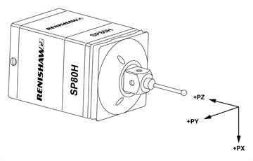
The probe orientation shown below is the orientation used in the SP80H probe product specification.

Probe attributes | Ultra-high accuracy scanning probe with three axis measurement (±PX, ±PY, ±PZ)* |
|---|---|
Orientation | Horizontal |
Size | 80 mm × 80 mm (3.15 in × 3.15 in) body, 150 mm (5.91 in) long including SH80 stylus holder |
Quill mounting | KM80: 80 mm × 80 mm quill to kinematic SP80 quill mount (standard) KM6080: 60 mm × 60 mm to 80 mm × 80 mm kinematic SP80 probe mount (option) SM80 : Shank mount and other custom made adaptor plates available - contact your Renishaw supplier for details |
Measurement range | 3-axis measurement: ±1.25 mm (PX)* / ±2.5 mm (PY, PZ)* |
Overtravel range | PY* and PX* protected by breakout of the kinematic joint to the SH80 PZ* has a mechanical bump stop |
Resolution of digital scales | 0.02 μm |
Measurement capability test to ISO10360-2** | Typically <1.0 μm MPETHN with a 60 mm stylus |
Scanning capability test to ISO10360-4** | Typically <1.5 μm MPETHN with a 60 mm stylus Time for scan = 74 s |
Return to zero | Approximately 1% of working deflection |
Spring rate | Approximately 2.5 N/mm (PX)* Approximately 1.6 N/mm (PY, PZ)* |
Stylus carrying capability | Renishaw M5 stylus range Maximum 300 g mass (unbalanced)*** Maximum 500 mm projection # |
Mass | SP80H probe body only: 860 g SH80 stylus holder: 185 g KM80 quill mount: 110 g |
Pull off force of SH80 | <20 N when using SCP80V - otherwise approximately 80 N |
Probe power supply | +9 V to +18 V @ 300 mA maximum dc |
System power supply (including IU80) | +5 V ± 0.25 V @ 1 A maximum dc |
SP80 probe outputs (X, Y, Z) | 1.5 V ± 0.25 V p-p. analogue quadrature signal (nominal 2.5 V zero crossing reference) |
Interfacing options |
|
Change rack system | SP80V mounted to on OEM supplied extension |
** Tested on a CMM with specification of 0.48 μm + L/1000 with touch and scanning deflections ≤ 0.15 mm
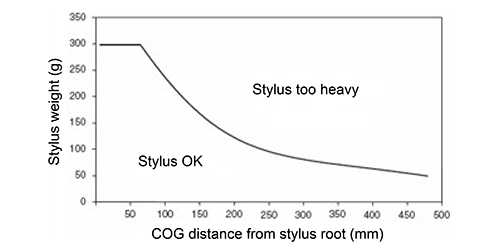
*** Stylus centre of gravity to be within area A of graph
# Longer stylus lengths may be carried subject to operating conditions - consult Renishaw for application assistance
SP80H specification
Stylus carrying capability
Due to the different orientation of the kinematics problems can occur when trying to support heavy styli on SP80H. Failure to reseat properly after the kinematics have been reseated may be observed with styli that have a moment at the stylus root greater than 200 g at 200 mm.
A graph representing a safe working moment range is shown below; this is based upon stylus weight and centre of gravity (COG) distance from the stylus root. It is advised that where possible customers should try and use styli configurations for SP80H that fall within these guidelines.

SCP80 stylus change port specification
Parameter | Description |
|---|---|
Type of rack | Passive, individual port for interchanging SH80 |
Mounting | Mounts to the MRS modular rack system Spaced and user definable positions along the length of the MRS |
Labels | User applied port number labels |
Collision protection | No collision protection in the SCP80 or MRS |
Operating orientation | Mounted parallel to the CMM bed |
Maximum stylus length | The MRS can be configured to accommodate an SH80 with the 500 mm maximum (vertical) stylus length. Additional MRS legs may be required |
Port entry tolerances | CMM positional accuracy of ±0.25 mm |
Port lid opening force | 2.6 N |
Force to detach SH80 | <20 N |
SCP80V stylus change port specification
Parameter | Description |
|---|---|
Type of rack | Passive, individual port for interchanging SH80 |
Mounting | Primarily vertical to be supplied by the OEM |
Labels | User applied port number labels depending on orientation |
Collision protection | No collision protection in the SCP80 or MRS |
Operating orientation | Mounted perpendicular to the CMM bed |
Maximum stylus length | Refer to graph - SP80H stylus carrying capability |
Port entry tolerances | CMM positional accuracy of ±0.25 mm |
Port lid opening force | 2.6 N |
Force to detach SH80 | <20 N |