Navigation
PHC10-3 PLUS introduction
The guide gives information on physical installation, system connections, communications and interface settings, as well as assistance in fault-finding during the installation of PHC10-3 PLUS.
WARNING: No attempt should be made to connect the PH10 PLUS system to any other any other system components as incompatibility will result in damage to the product.
The guide should be read in conjunction with the PH10 PLUS series user's guide in order to fully understand the system's features, capabilities and operation.
The PH10 PLUS series of motorised probe heads can only be used in conjunction with the PHC10-3 PLUS when part of an OEM system installation. PHC10-3 PLUS has replaced the PHC10-2 and provides support for RS232 and USB communications (IEEE is no longer supported). PHC10-3 PLUS uses an external power supply for the PH10 PLUS series of heads, manages all the head functions and communicates via a suitable interface with the CMM's computer. PHC10-3 PLUS does not manage the probe functions but does have the provision for an interface to be fitted.
Rear panel layout
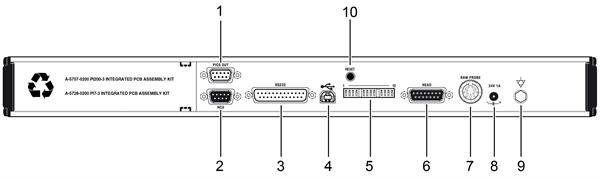
Key | Description |
|---|---|
1 | 9-way D-type plug for PICS output |
2 | 9-way D-type connector to HCU2 |
3 | 25-way D-type plug RS232 communications connector to CMM computer |
4 | USB type “B” socket |
5 | PHC10-3 PLUS configuration switches |
6 | 15-way D-type connector to probe head |
7 | 7-pin DIN raw probe connector to probe interface or multiwire input for internal interfaces |
8 | DC power jack |
9 | Equipment bond point |
10 | Controller reset button |