QUANTiC™ optical incremental encoder series
Made for manufacturing
The QUANTiC encoder system integrates Renishaw's filtering optics design and interpolation technology to create a super-compact, robust, incremental open optical encoder. QUANTiC encoders are easy to use with exceptionally wide installation and operation tolerances, along with built-in calibration functions.
QUANTiC readheads offer digital output and a new analogue output variant with a wide variety of configurations and linear or rotary scale options. Speeds up to 24 m/s can be achieved to meet the most demanding motion control requirements.
Detailed diagnostic information can be accessed by using the ADTpro-100 standalone encoder diagnostic tool and the ADTi‑100 diagnostic tool, both of which are compatible with the ADT View software. They aid optimisation of encoder installation and in-field fault finding to satisfy the most demanding motion control applications.
Downloads: datasheets and technical documents
Further information about the technical specifications of the QUANTiC encoder series, such as datasheets and installation guides, are available from our technical downloads section.
Watch our introduction to QUANTiC incremental encoders
What form of motion do you need to measure?
Linear
Scale type | Scale name | Accuracy | Scale pitch | Coefficient of thermal expansion at 20 °C | Supplied length |
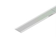
Stainless steel tape
| RTLC40 | 40 µm (high accuracy): ±5 µm/m | 40 µm | 10.1 ±0.2 µm/m/°C | 10 m (> 10 m on request) |
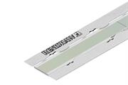
Stainless steel tape with track option
| RTLC40 with optional FASTRACK™ | 40 µm (high accuracy): ±5 µm/m 40 µm: ±15 µm/m | 40 µm | 10.1 ±0.2 µm/m/°C | Up to 10 m (> 10 m on request) |
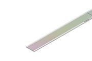
| Narrow stainless steel tape
| RKLC40-S/RKLC40H-S | 40 µm (high accuracy): ±5 µm/m 40 µm: ±15 µm/m | 40 µm | Matched to substrate material when scale ends are fixed with end clamps | Up to 20 m (> 20 m on request) |
Partial arc
Scale type | Scale name | Accuracy | Scale pitch | Coefficient of thermal expansion at 20 °C | Supplied length |
Narrow stainless steel partial arc
| RKLC40-S | 40 µm: ±15 µm/m | 40 µm | 10.1 ±0.2 μm/m/°C | 20 m (> 20 m on request) |

Rotary
Scale type | Scale name | Graduation accuracy (depending on ring diameter) | Scale pitch | Coefficient of thermal expansion at 20 °C | Ring diameter |
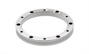
Stainless steel ring
| RESM40 | ±3.97 to ±0.38 arc seconds | 40 µm | 15.5 ±0.5 µm/m/ °C | 52 to 550 mm |
Key benefits

Easy installation and set-up
Increased installation and operational tolerances whilst maintaining metrological performance. Low cost of ownership achieved through reduced installation and set-up times.

Robust position measurement over contamination
Signal filtering to eliminate non-harmonic signal frequencies, ensuring low Sub-Divisional Error (SDE) and minimal signal variation over dirt or contamination on the scale.

High speed
Speeds up to 24 m/s achieved to meet the most demanding motion control requirements.
The quick and easy installation of parts is absolutely one of the key factors for punctual delivery. QUANTIC encoders have wide installation tolerances that enable faster installation. Also, by monitoring the colour of the set-up LED on the readhead, we can quickly determine if the signal strength is up to standard and whether the installation is successful. These features save time, reduce costs and give us great confidence.
Kovery (South Korea)
Optional Advanced Diagnostic Tools
Renishaw optical encoders can generally be installed using just the set-up LED on the readhead but an Advanced Diagnostic Tool (ADT) can be used to help with more challenging installations. These tools provide detailed real-time encoder data to assist in fault finding and to avoid lengthy machine downtime.
The QUANTiC encoder is compatible with two Advanced Diagnostic Tools: the ADTpro-100 and the ADTi-100.
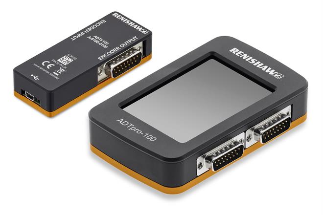
The ADTpro-100:
- Is a handheld, standalone encoder diagnostic tool – no computer or other equipment is required.
- Features an integral colour touch screen.
- Is easy and intuitive to use with plug-and-play functionality to aid system set-up and calibration.
- Interfaces with the optional ADT View computer software, which allows encoder data to be saved as a record of the system setup and performance. ADT View can also be used to update the ADTpro-100 firmware
The ADTi-100:
- Interfaces with the intuitive ADT View computer software.
- Provides comprehensive real-time encoder data feedback to aid more challenging installations and diagnostics.
- Assists system set-up, calibration and signal optimisation along the entire axis.
- Allows encoder data, such as signal strength vs position along the axis, to be saved as a record of the system setup and performance.
Both the ADTpro-100 and ADTi-100 can be used standalone or in-line, connected between the readhead and the controller as part of the control loop.
Discover our range of open optical encoders designed to meet your industrial automation needs.