MODUS™ Planning Suite
Master your CMM with minimal effort and improved efficiency with MODUS Planning Suite.
The MODUS Planning Suite is designed to provide MODUS users with a set of automated shortcuts to solve frequent challenges in part programming, maximising the efficiency of their REVO® CMM head with easy-to-use specialised software applications. The MODUS Planning Suite applications allow users to plan measurement paths around complex geometry components with minimal effort and improved efficiency.
Harnessing advanced planning technology, the software provides offline tools with simulated motion to create DMIS code representing collision‑free part measurement.
There are currently three modular applications separately available for the MODUS Planning Suite platform:
MODUS Blade planner
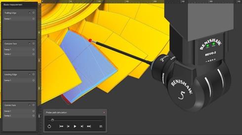
Blade measurement
The full blade inspection option in MODUS Blade planner enables the user to plan sweep scans on concave, convex, leading and trailing edge surfaces.
The settings and measurement strategies allow the user to customise the measurement paths, providing the ability to control the number of sweeps per surface and to change the direction of measurements between longitudinal and transverse sweeps.
Section measurement
The Blade planner module offers two methods to measure blade sections:
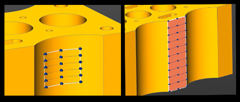
- Sweep scans over sections with the option of joined sweeps.
High density sweep scans cover the sections where airfoil data is collected, whilst low density sweep scans occur between the sections where no data is collected. This method also reduces the number of approach and retract moves, hence reducing cycle time. - Section curve scans on faces
Curve scans are created on the concave and convex faces, and full sweep scans are created on the leading and trailing edges.
MODUS Planning Suite generates the required DMIS to measure the airfoil surface. MODUS 1.9 can then execute this DMIS and allow the user to perform the airfoil analysis on each section.
Patch measurement
To provide the tools to plan the path for the complete blade and surrounding surfaces, the MODUS Blade planner module incorporates all the selection methods available in MODUS Patch planner:
- Create a patch from an outline of points (Area)
- Select a patch from selected faces (Face)
- Create a patch from points on a centreline
- Create a patch from CAD edges
See a full description of the MODUS Patch planner module for MODUS Planning Suite below.
Other modular applications separately available for the MODUS Planning Suite are:
MODUS Patch planner
Until now, users had to define their own paths for surface sweeps using manual manipulation tools to avoid collisions. Now, the new MODUS Patch application delivers the most efficient measurement path with the REVO RSP2 sensor, quickly and easily, with automatic path planning.
- Create patches from points
Define a sweep path by creating a series of points to create a four-sided area on the CAD. - Create patches from a face
Click on the CAD model to select a surface or set of connected surface points to define the patch. - Create patches from CAD edges
Use the CAD edges to determine the sweep path. A MODUS slice can also be selected as an edge using this tool. The software generates the shortest path when start and end points are selected. - Create patches by drawing a centre line
Define a sweep path by creating a series of centre line points on a surface.
Once the selection method is established, edits to the sweep width, direction and other characteristics can be made in the settings menu, if required.
Other modular applications separately available for the MODUS Planning Suite are:
Point and face sweep generation
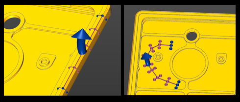
CAD edge and centre line sweep generation
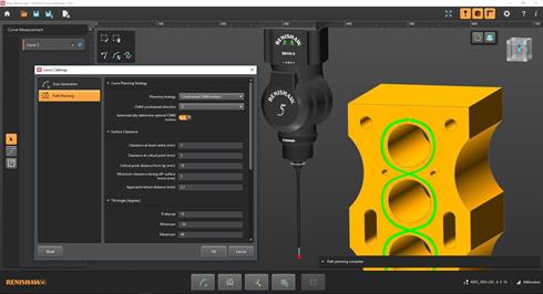
MODUS Curve planner
The curve planning module includes two options: RSP2 Curve and RSP3 Curve. RSP3 provides increased capability to measure complex geometries using different probe assemblies.
Curves can be defined by the selection of edges from the CAD model or by clicking points on a plane.
Create curve on CAD edges
Curves are defined by either selecting edges of the CAD model or edges of a slice created using MODUS.
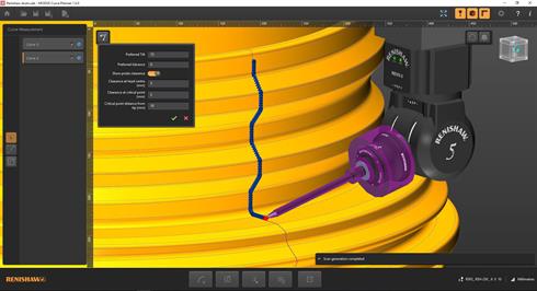
Sketch a curve on a plane
Curves are defined by clicking a number of points on the plane. A spline is fitted to create the path.
Additional choices for the RSP2 Curve option
Create an edge offset on a plane
Once the required plane is selected on the CAD model and the edges are chosen, an offset value will be applied.
A set of graphical options complements the software settings, making it easy to join and trim paths, which delivers the most efficient result.
Multiple edges can be selected on a single face and then joined. This creates measurement that does not leave the surface, reducing the time taken for moves between measurements.
Create an edge offset avoiding features on a plane
Once a plane and edge have been selected, this option automatically detects and avoids geometry in the CAD model that the measurement needs to avoid, updating the path as offset values are adjusted.
The user can select a single edge on each curve measurement.
Additional choices for the RSP3 Curve option
Fixed head angle segments
The RSP3 probe measures at fixed head angles and the probe may come off surface during some curve scans so that the head angle can be changed.
The RSP3 Curve element in the MODUS Curve module provides the ability to define segments of measurement where the probe will not come away from the surface. This enables the user to meet the requirements of high accuracy zones along a single curve path.
Quick and easy to use
Once the curve is selected, editing parameters such as the scan direction, can be easily done in the settings.
For both methods of defining curves the application incorporates constrained CMM motion, which reduces the CMM axis motion when measuring curves on a plane.
The combination of constrained axes with collision-free motion planning delivers a significant reduction in programming times for quick and effective curve measurement.
Other modular applications separately available for the MODUS Planning Suite are:
Constraining the machine axis motion to a single plane improves accuracy and repeatability.
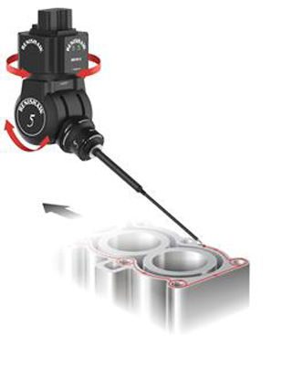
Why constrain the CMM motion?
Constraining one or more axis of the CMM maximises the use of REVO® head motion and minimises the motion of the CMM. By constraining two axes and moving only in the one axis parallel to the plane being measured, machine bending is in the plane that's being inspected and as such no error is seen. This presents the opportunity to measure parts quicker or achieve a higher level of accuracy from an existing machine.
For example, when measuring the flatness of a cylinder block sealing face, constraining two axes enables the machine to be operated faster without introducing measurement errors. Ideally, the Z-axis of the machine is used to move the REVO up and down as it has the lowest moving mass and X and Y are constrained. In this case, there are no bending forces, just compression/tension along the length of the quill where it is very stiff. If Z isn't possible, then X (constrained in Z and Y) is the next best as it has the next lowest moving mass. Using Y will still benefit from this method compared to moving the head towards and away from the part as done with traditional 5-axis scans.
Additional information
Help and training
The installation package provides tutorial videos and sample CAD models to assist in training.
Software compatibility
DMIS code from MODUS Planning Suite must be run in MODUS. For full capability MODUS 1.9 is required.
CAD models must be in the .Sab format.
Hardware compatibility
The supported hardware combination for this version of MODUS Planning Suite is REVO-2 with the RSP2 scanning probe.