Navigation
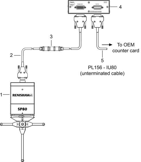
Connecting SP80 / SP80H to IU80 and OEM counter card
| Key | Description |
|---|---|
| 1 | SP80 / SP80H probe (shown for mounting to CMM via KM80) |
| 2 | PL157 - SP80 to Lemo adaptor cable |
| 3 | PLM6 / 7 / 8 / 9 - standard machine cable |
| 4 | IU80 interpolator box |
| 5 | PL156 - IU80 output cable to OEM counter card (supplied unterminated) |
The output of the IU80 can be connected directly to the CMM controller using an unterminated PL156 cable.
IU80 output 26-way HDD | Signal | Electrical characteristics | Colour |
|---|---|---|---|
| 1 | X DigA | EIA-422A | Red |
| 2 | N/C | ||
| 3 | RESET | TTL | White / blue |
| 4 | ERROR | TTL | Blue |
| 5 | N/C | ||
| 6 | Z DigB | EIA-422A | |
| 7 | N/C | ||
| 8 | Probe Present | TTL | Yellow / blue |
| 9 | Green_LED_OFF | TTL | Yellow |
| 10 | Red_LED_ON | TTL | White |
| 11 | X DigA | EIA-422A | Black |
| 12 | X DigB | EIA-422A | Brown |
| 13 | X DigB | EIA-422A | Violet |
| 14 | Y DigA | EIA-422A | Orange |
| 15 | Y DigA | EIA-422A | Pink |
| 16 | Y DigB | EIA-422A | Turquoise |
| 17 | Y DigB | EIA-422A | Grey |
| 18 | 0 V | N/C | |
| 19 | N/C | ||
| 20 | Z DigA | EIA-422A | Red / blue |
| 21 | Z DigA | EIA-422A | Green / red |
| 22 | Z DigB | EIA-422A | Yellow / red |
| 23 | +9 V to +18 V | 300 mA max | White / red |
| 24 | +5 V | 1 A max | Red / black |
| 25 | 0 V | Red / brown | |
| 26 | N/C | N/C | |
| Shell | Screen | Screen |
Probe and IU80 power supply
The IU80 must be provided with two power supplies.
+9 V to +18 V @ 300 mA max to supply the SP80 probe and
+4.75 V to 5.25 V @ 1 A max to supply the IU80.
Power must originate from either the OEM's controller or from a Renishaw CC6 counter card.
IU80 output signal format
The signals produced by IU80 are in EIA-422-A differential square wave format and in quadrature for each probe axis. The sign definition for the signals is a positive count when DigA leads DigB.
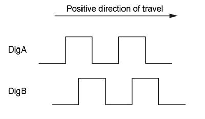
The IU80 provides a minimum edge separation of 90 ns between any of the edges of a pair of quadrature signals.