Optical encoders frequently asked questions
General
What is the warranty for Renishaw encoders?
Every Renishaw optical, laser, inductive and magnetic encoder product comes with a 2 year warranty and our industry-leading repair-by-exchange programme which immediately replaces a product from local inventory to ensure machinery downtime is kept to an absolute minimum.
What solvents can be used to clean scales and readheads?
The recommended cleaning solvents depend upon the particular encoder system used and are detailed in the system installation guides.
Is it possible to remove adhesive tape scale and re-use it?
No. When scale is removed the adhesive backing tape will no longer be effective. Also, the act of removing the scale may damage it or affect its metrology performance.
What is the pin assignment for connectors on Renishaw readheads?
Where possible, Renishaw have standardised pin assignments for the common 15 way D type connectors used on analogue and digital output readheads and interfaces. Also, where possible, other connector types have industry standard pin assignments. All pin assignments for Renishaw encoder systems can be found in the system installation guides.
Are male (plug) or female (socket) connector types used on Renishaw encoders?
As a general rule, male connectors are used where incremental signals are output from the encoder and female connectors are used where incremental signals are received from the encoder (for example into an intermediate interface). Connector types and whether they are plugs or sockets, are detailed in the system installation guides.
Why is there a difference between theoretical speed and achievable maximum speed for digital encoder systems with clocked outputs?
For clocked output systems, Renishaw quotes the clock frequency option as the recommended counting frequency of the receiving electronics. This is greater than the actual clocked output frequency of the encoder due to a safety factor being added. This safety factor allows for clock oscillator tolerances, line driver, cable and line receiver skews, cyclic error (SDE) and jitter, which all contribute to a lower minimum edge separation of the incremental signal than that calculated for a theoretically perfect system.
For example, a 20 MHz Ti TONiC™ interface option has an actual clocked output of 15 MHz, resulting in a maximum speed of 1.35 m/s for a 0.1 μm resolution encoder. Theoretical maximum speed for this system would be 1.5 m/s, although, for the reasons stated above, this would not be possible.
Analogue signal bandwidth will also restrict maximum speed to an upper limit irrespective of the clocked output of the encoder. In the case of the TONiC system, this limit is 10 m/s.
How do I know whether the encoder is functioning correctly?
The encoder has an integral set-up LED on the readhead and/or interface. This LED indicates if the readhead is powered and the quality of the encoder set-up. More information about specific systems can be found in our installation guides.
How should the outer and inner shield of the readhead cable be connected to single shield extension cable?
The inner shield of the readhead cable must be connected to the 0 V line within the intermediate connector and the outer shield of the readhead cable must be connected, via the (metallic/conductive) connector shell, to the shield on the extension cable, as shown in the diagram below. Note: The outer shield should form a continuous screen from readhead body around connector to customer electronics.
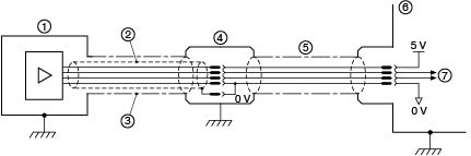
1. Readhead
2. Inner shield
3. Outer shield
4. Connector
5. Single shield extension
6. Customer electronics
7. Output signals
What is the flex life of the readhead cable?
The flex life of all readhead cable types is tested to > 20 x 106 cycles.
Depending on the diameter of the cable, the cable flex life is tested at either 20 or 50 mm bend radius. Please refer to the relevant encoder system installation guide.
Are Renishaw readhead cables suitable for use in a robotic applications that require the cable to be flexed?
If the readhead cable minimum bend radius is not exceeded (see relevant data sheet) then the cable will have a minimum flex life of 20 000 000 operations. However the cable is not designed for applications that rotate (twist) the cable along its length. It is not recommended to bend or flex UHV readhead cables as this will damage the cable.
What is a ‘clocked output option' and how to choose the correct clock frequency?
The 'clocked output option' should be used when it is required to limit the maximum frequency the encoder can output. Without limiting the output frequency miscounting of the receiving electronics will occur when its maximum input frequency is exceeded. This is particularly important when the encoder is either stationary (or moving very slowly) when it is possible to get a rapid changes in output state. The clocked output frequency should be chosen to be equal or less than the maximum input frequency of the receiving electronics. It should be noted that choosing a clocked frequency much less than the input frequency will result in a reduction of maximum speed of the encoder.
What is the maximum length of extension cable without signal distortion?
Extension cable length information for specific systems is detailed in the installation guides.
What is the MTBF (Mean Time Before Failure) for Renishaw optical encoders ?
Please refer to the example below for RGH24/RGH25 readhead reliability:
MTBF (M) = pt / n
Where:
p: installed population of readheads
t: average length of service
n: total relevant failures
From our records (yearly production figures and failure data), readhead MTBF in continuous use is 2,013 years.
As a practical example, if a customer has 28 three axis machines, the installed readhead population (p) is 84. The mean interval (t) between any readhead failure (i.e. n = 1) may be calculated by rearranging the MTBF formula:
t = Mn / p = (2,013 years * 1) / 84 = approximately 24 years
Therefore with a total of 84 readheads running 24 hours per day, this customer could expect a single readhead failure approximately once every 24 years.
This information is not a guarantee of product reliability and does not represent a condition of warranty.
For MTBF data for other Renishaw encoder series, please contact your nearest Renishaw representative.
Why does Renishaw recommend the hub adhesive mounting surface profile?
The recommend gluing profile allows the adhesive to adapt to a greater range of temperature extremes. It also ensures accurate location of the disc onto the mounting face of the hub.
Do I need to calibrate my Renishaw encoder system ?
ATOM™, TONiC™, VIONiC™ and QUANTiC™ need to be calibrated to optimise performance.
What are the benefits of using the Renishaw Advanced Diagnostic tools?
The three models of Renishaw Advanced Diagnostic Tools offer a range of functionality for incremental and absolute optical encoders.
ADTi-100
The ADTi-100 is compatible with a selection of Renishaw incremental optical encoders and works with ADT View software to offer a visual indication of the following readhead outputs:
- Signal strength Display signal size, reference mark phasing and limit switches, where applicable, and allow system calibration to be started.
- Lissajous plot Display the readhead output signal quality.
- Signal strength versus position A plot of signal strength along the full axis can be used to optimise the installation, aid diagnostics and confirm that field service has been carried out correctly.
- Velocity Display the current system velocity.
- Digital Read Out (DRO) Digitally display the system position.
ADTa-100
The ADTa-100 includes an array of seven multicolour LEDs to indicate signal strength. This allows the readhead setup to be quickly checked without requiring a PC or laptop. When connected to a Windows PC, ADTa-100 interfaces with ADT View software to display the following readhead outputs for Renishaw absolute encoders:
- Digital Read Out (DRO) Digitally display the system position.
- Signal strength versus position A plot of signal strength along the full axis can be used to optimise the installation, aid diagnostics and confirm that field service has been carried out correctly.
- For serial interfaces that include a set zero function, this can be activated through the ADT View software interface.
ADTpro-100 (available for pre-order)
The ADTpro-100 offers a colour touch screen, displaying detailed encoder information without the need to connect to an external computer. No other additional set-up equipment is required. ADTpro-100 is compatible with Renishaw incremental optical encoders. Compatibility with Renishaw absolute optical encoders will be added soon.
- It is equipped with a USB port which enables it to be used with ADT View when a larger display is required.
- It can also be used in secure working areas as it does not have a camera or wireless capability, which complies with the strictest production site access controls.
Scales
What is the range of optical scale types offered by Renishaw?
Please refer to our optical encoders' range of scales webpage.
What influences the choice of incremental scale pitch (period)?
Renishaw incremental optical encoder systems offer 20 µm or 40 µm scale pitch, depending on the particular system. (In general, larger scale pitches offer more generous installation tolerances and higher speeds, whereas smaller scale pitches offer higher resolutions and lower SDE (Sub Divisional Error)).
What is the difference between graduation accuracy, system accuracy and installed accuracy in relation to angle encoders?
Graduation accuracy is the accuracy with which the scale graduations are written to the ring during manufacture.
System accuracy is graduation accuracy plus readhead cyclic error (SDE).
Installed accuracy is the accuracy a customer can expect from the encoder once installed onto the working axis. This will include system accuracy, but is also affected by a number of other factors, predominantly eccentricity of the ring/disc.
For smaller rings/discs, eccentricity is likely to be the largest contributor to installed accuracy. Depending on the system, either system accuracy or installed accuracy is specified, although all ring calibration certificates show a graph of typical installed accuracy when installed in accordance with the recommended guidelines detailed in installation guides. For application advice, please contact your nearest Renishaw representative.
Does Renishaw produce any incremental encoder systems that operate with a fine pitch scale?
Renishaw produces incremental encoders with either 20 μm or 40 μm pitch scales. Although there are finer pitch encoder systems available, it does not necessarily follow that these systems give a better overall performance. Finer pitch systems can be more difficult to set up and can have limited speed capability and poor dirt immunity. Also, with effective incremental signal processing techniques, many Renishaw encoder systems give comparable accuracy and cyclic error (SDE) to finer pitch systems.
What scale should be used for partial arc applications?
For partial arc applications we recommend using the RKL range of encoder scales. RKL scales are thin and highly flexible which enables easy installation around partial arcs and best accuracy when compared to other types of tape scale.
What readhead should be used for partial arc applications?
For an absolute partial arc application, a RESOLUTE linear readhead compatible with RKLA encoder scales should be used.
For an incremental partial arc application, it is possible to use a QUANTiC, VIONiC or TONiC partial arc compatible readhead, or an ATOM* or ATOM DX* linear readhead. The choice of readhead will be dependent on the specific requirements of the application.
* RKLF40-S scale only
What mounting surface can be used for partial arc applications?
It is possible to measure a partial arc using RKL encoder scales on all metallic mounting surfaces with a coefficient of thermal expansion between 8 and 24 ppm/oC such as aluminium, steel or titanium. For other materials please contact your local Renishaw representative.
Compliance
Are Renishaw optical encoders and scales RoHS compliant?
Yes, please refer to our compliance certificates webpage.
Are Renishaw optical encoders and scales using minerals from conflict areas ?
Please refer to our compliance certificates webpage.
Do Renishaw optical encoders and scales comply with EU legislation (CE declarations of conformity)?
Yes, please refer to our compliance certificates webpage.
Absolute
What are the advantages of absolute over incremental encoders?
A key reason for selecting absolute over incremental technology is in consideration of a machine's start-up cycle. An axis fitted with incremental encoders typically has to hunt to locate a reference mark to establish the datum or zero position. Renishaw's absolute encoders provide exact position immediately at switch-on without any need for movement of the axis. Locating reference marks can be a real problem for multi-axis machines, especially if the axes are not orthogonal or if the payload is sensitive or fragile.
Often, absolute encoders remove the need for a separate encoding system for motor commutation. Since no motion is necessary to determine absolute position, the same encoder can be used for motion feedback and motor commutation.
Finally, Renishaw absolute encoders overcome the speed/resolution trade-off which often restricts the performance of incremental axes. Position is provided on-demand, avoiding the very high bandwidth needed to transmit high resolution incremental signals on fast-moving axes. For example, RESOLUTE can provide feedback with 1 nm resolution on axes which move at up to 100 m/s. With an incremental encoder, a bandwidth of 100 GHz would be required to achieve that!
Does the RESOLUTE encoder system support SSI protocol?
RESOLUTE does not support SSI. SSI is a very simple serial communication protocol which does not support any data integrity checking. Instead, RESOLUTE is available with a similar protocol, known as “BiSS® C Unidirectional”. This is almost as simple, but adds reporting error and warning information and avoids the risk of uncontrolled axis motion by protecting the position data from corruption with a CRC (cyclic redundancy check).
Incremental
What is the difference between the VIONiC and TONiC encoder series?
Please find below Renishaw's incremental super-compact products' main differentiating features:
Features | VIONiC | TONiC |
Outputs | Digital resolutions from 5 µm to 20 nm direct from the readhead | Analogue 1 Vpp only. |
Sub-Divisional Error | Typically < ±15 nm | Typically < ±30 nm |
Jitter (RMS) | Down to 1.6 nm | Down to 0.7 nm |
Maximum speed | 12 m/s | 10 m/s |
Does Renishaw produce any incremental encoder systems that operate with a fine pitch scale?
Renishaw produces incremental encoders with either 20 μm or 40 μm pitch scales. Although there are finer pitch encoder systems available, it does not necessarily follow that these systems give a better overall performance. Finer pitch systems can be more difficult to set up and can have limited speed capability and poor dirt immunity. Also, with effective incremental signal processing techniques, many Renishaw encoder systems give comparable accuracy and cyclic error (SDE) to finer pitch systems.
What do CAL and AGC do?
CAL refers to a system calibration routine which is an essential operation that completes readhead set-up, optimising incremental and reference mark signals. Calibration settings are stored in local memory so optimum performance is obtained immediately after the power is cycled. Different interfaces have their own calibration procedures.
Renishaw's range of high performance incremental encoders incorporate a DC light servo, this is a control loop which maintains the mean reflected light incident on the photodetector by controlling the drive current for the encoders light source. The DC servo effectively removes the effects of temperature variation, some forms of scale contamination, scale reflectivity variation and IRED ageing.
The AGC (Auto Gain Control) system is a control loop which measures the AC component of the incremental encoder signals and adjusts target for the DC light servo. This system can be used to compensate for mechanisms which affect the AC performance of the readhead e.g. grease/fingerprints on the scale. It can be successfully used to maintain a consistent 1 Vpp output signal amplitude. The AGC function can be toggled where necessary.
In all cases maximum performance i.e. widest dynamic range of these systems can be obtained by optimising the installation of the encoder system.
CAL and AGC are offered on QUANTiC, VIONiC, TONiC and ATOM.
What is the position (time) delay of incremental encoder signals?
The time delay through an incremental encoder system depends on many factors, including the output type, optical stage, analogue and digital electronics stages, line driver/receiver and cabling design/length. These figures are known but difficult to document therefore for exact application advice, please contact your nearest Renishaw representative.
Absolute - EVOLUTE™
What is the difference between the EVOLUTE and RESOLUTE encoder series?
EVOLUTE and RESOLUTE are the 2 absolute encoder series Renishaw currently offers. Their differences in technical specification are as follows:
| Feature | EVOLUTE | RESOLUTE |
| Resolution | 50, 100 or 500 nm | 1, 5 or 50 nm |
| Accuracy | ±10 µm/m | ±5 µm/m (RTLA) |
| SDE | ±150 nm | ±40 nm |
| Jitter | ≤10 nm RMS | ≤10 nm RMS |
| Rideheight (tolerance) | 0.8 ± 0.25 mm | 0.8 ± 0.15 mm |
| Yaw (tolerance) | ±0.75° | ±0.5° |
| Pitch (tolerance) | ±0.5° | ±0.5° |
| Roll (tolerance) | ±0.5° | ±0.5° |
Which applications is the EVOLUTE series recommended for?
The EVOLUTE series brings improved installation tolerances for an absolute encoder, ensuring fast and easy installation without the need for fine adjustment. This makes EVOLUTE encoders well suited to high volume OEM applications where machine build time is critical as time saved in component installation allows shorter manufacturing lead times and ultimately higher profitability.
Which protocols does the EVOLUTE series support?
The EVOLUTE encoder supports BiSS C, Mitsubishi (J4 series of servo drives and the MDS-D2/DH2/DM2/DJ drives for machine tool applications) and Yaskawa (Sigma-5 and Sigma-7 SERVOPACKs) serial communication protocols.
Incremental - QUANTiC™
Which scales are available with QUANTiC encoders?
The QUANTiC readhead is compatible with the RTLC40-S stainless steel tape scale with bi-directional optical IN-TRAC reference marks and the FASTRACK™ RTLC40 track system, as well as RESM40 rotary (angle) rings.
Which applications are the QUANTiC series recommended for?
The QUANTiC encoder has been designed for manufacturers and system integrators with its exceptionally wide installation tolerances, whilst maintaining the super-compact form factor and excellent metrology. A major application of QUANTIC encoders will be stage manufacturers looking for an easy to install system, with the potential to dead reckon, reducing installation times and increasing throughput. Other applications will include multi-axis systems, semiconductor manufacturing, and applications with long axis lengths.
Incremental - VIONiC™
What is the difference between the VIONiC and TONiC encoder series?
Please find below Renishaw's incremental super-compact products' main differentiating features:
Features | VIONiC | TONiC |
Outputs | Digital resolutions from 5 µm to 2.5 nm direct from the readhead | Analogue 1 Vpp only. RS422 digital resolutions from 5 μm to 1 nm available when connected to a Ti, TD or DOP interface |
Sub-Divisional Error | Typically < ±15 nm | Typically < ±30 nm |
Jitter (RMS) | Down to 1.6 nm | Down to 0.7 nm |
Maximum speed | 12 m/s | 10 m/s |
What scales are available with VIONiC readheads?
The VIONiC™ readheads are complemented by the latest evolution of RTLC-S stainless steel tape scale with bi-directional optical IN-TRAC™ reference marks, FASTRACK™ / RTLC track systems and REXM ultra-high accuracy angle encoder in addition to established RSLM stainless steel scale, RELM high accuracy low expansion, high stability scale and RESM rotary rings.
What applications is the VIONiC series recommended for?
VIONiC has been designed to reduce overall system size to the minimum achievable for a high-performance system, whilst delivering class-leading performance in terms of cyclic error (SDE), jitter and accuracy. A major application for VIONiC will be linear motors which depend on high controller gains and large bandwidths in order to minimise position settling time and allow constant velocity motion. Velocity errors are caused by inaccuracies in the encoder output, which are in turn amplified by the control gain: VIONiC offers linear motor designers the best all-round encoder solution for velocity (torque) ripple. Other potential applications include small translation stages, multi-axis platforms, large housed DDR motors, semiconductor, medical and those with limited space but the most demanding performance requirements.
Incremental - TONiC™
How are TONiC encoder interfaces mechanically connected to a machine or control cabinet?
TONiC interfaces can be connected directly to panel mounted 15 way D-type input sockets fitted with locking posts as they are similar in size to a standard 15 way D-type plug. Alternatively, Renishaw can supply a simple bracket which connects the TONiC interface to a mounting surface by means of two M4 screws. The part number for this is A-9690-0015.
Incremental - ATOM DX™
Which scales are available with ATOM DX encoders?
The ATOM DX readhead is compatible with the RTLF stainless steel tape scale, the RCLC glass spar scale, the RCDM rotary (angle) glass disc and the CENTRUM™ CSF40 rotary (angle) stainless steel disc.
What is the connector on the ATOM DX top exit variant?
The connector on the ATOM DX readhead is a 10 way JST and the mating connector is 10SUR-32S.
Do you offer cables for top exit readheads?
Yes, we offer cables with a 15 way D-type connector or a 10 way JST (SUR) connector in four lengths including 0.5, 1, 1.5 and 3 meters. Part number details can be found in the ATOM DX data sheet.
Incremental - ATOM™
What considerations need to be taken when using ACi interfaces?
The ACi interface has been designed to be integrated within a customer application and as such, the design has no casing. In order to ensure good performance, the end user must provide adequate shielding (to reduce RF emissions and susceptibility) and to provide electrical and mechanical connection to the cable screens. In general, best performance is obtained when the shields are connected to FG (field ground).
What influences the choice of interface when using ATOM?
There are many factors that might influence you choice of interface to use with the ATOM readhead. Some of the keys ones might be resolution, maximum system speed, SDE (Sub-Divisional Error) or the size of the interface. The following table compares these factors.
Interface type | Resolutions | Maximum speed | SDE | Interface size (L x W x H) | |||
Ti | 5 µm to 1 nm | 10 µm to 2 nm | 10 m/s | 20 m/s | < ±50 nm | < ±100 nm | 67 mm x 40 mm x 16 mm |
Ri | 5 µm to 0.5 µm | 10 µm to 1 µm | 10 m/s | 20 m/s | < ±100 nm | < ±150 nm | 52 mm x 40 mm x 16 mm |
Ri | 0.2 µm to 50 nm | 0.4 µm to 0.1 µm | 0.8 m/s | 1.6 m/s | < ±125 nm | < ±220 nm | 52 mm x 40 mm x 16 mm |
ACi | 1 µm to 0.1 µm | 2 µm to 0.2 µm | 6.5 m/s | 13 m/s | < ±100 nm | < ±150 nm | 25 mm x 25 mm x 9.5 mm |
ACi | 50 nm to 10 nm | 0.1 µm to 20 nm | 0.35 m/s | 0.7 m/s | < ±125 nm | < ±220 nm | 25 mm x 25 mm x 9.5 mm |
What is the shortest measurement length over which ATOM can be successfully calibrated?
ATOM can be successfully calibrated (including reference mark) over an axis travel of ±120 µm (although multiple passes may be required over this distance if the initial signal levels are very low or high).
Can short lengths (< 50 mm) of RTLF scale be rigidly glued to the substrate?
Yes, in most cases when space is a premium, the RTLF scale can be rigidly glued directly to the substrate. For further advice on any specific application, contact your nearest Renishaw representative.
How immune is ATOM to oil contamination?
The ATOM and other "optically filtering" encoder systems from Renishaw can operate with moderate levels of grease or oil contamination due to the unique way the optics function. The only detrimental effect is to lower the incremental signal amplitude - which can be compensated with the AGC function.
Please refer to our glossary for the definitions of the technical terminology used on this page.