Optical encoders frequently asked questions
General
What is the warranty for Renishaw encoders?
Every Renishaw optical encoder product comes with a 2 year warranty. In the unlikely event that a Renishaw encoder fails, we will replace it right away, to ensure minimal machine downtime.
How does Renishaw ensure delivery of high quality products?
All key manufacturing stages, from PCB assembly and machining of bodies to cable assembly and final readhead assembly / test are carried out in-house. Unlike many other encoder companies, our scales are also made in-house. This philosophy ensures we maintain total control of product quality at every step.
Can Renishaw encoders be customised?
Renishaw encoders are available with a wide range of specification options, such as cable lengths, mounting options, serial interfaces, shaft sizes, resolution and electrical options. This flexibility provides encoders well suited to most applications but, if you have a specific requirement, such as for example a custom cable length, please contact your local Renishaw representative.
Open optical encoders
Does the RESOLUTE™ absolute encoder system support SSI protocol/serial interface?
The RESOLUTE encoder does not support SSI. SSI is a very simple serial communication protocol which does not support any data integrity checking. Instead, the RESOLUTE series is available with a similar protocol, known as BiSS® C (unidirectional). This is almost as simple as SSI, but also provides error and warning information and avoids the risk of uncontrolled axis motion by protecting the position data from corruption with a CRC (cyclic redundancy check).
How are the Renishaw open optical encoder series different?
Our open optical encoder comparison table details the differences between the ATOM™, ATOM DX™, TONiC™, VIONiC™, QUANTiC™, RESOLUTE™, EVOLUTE™ encoder series.
How to choose the most suitable interface for your open optical encoder?
Renishaw provides a range of interfaces compatible with specified incremental open optical encoders:
| Interface | Description | Compatible encoder readhead |
| Ti | High performance interface | ATOM™, TONiC™ |
| TD | Dual resolution interface | TONiC |
| DOP | Dual output interface | TONiC |
| Aci | Compact PCB interpolator interface | ATOM |
| Ri | 15-way D-type interface | ATOM |
Scales
What are the features of the different optical encoder scales?
Renishaw provides a wide range of linear, rotary, partial arc and multi-DoF scales for open optical encoders.
- Linear encoders deliver straight-line motion measurement - usually X, Y or Z axes.
- Rotary (angle) encoders are available for angular position measurement and the motion control of rotating elements.
- Partial arc encoders measure rotation of less than a complete turn by wrapping the scale around drums, shafts or arcs.
- Multi-DoF encoders measure multiple degrees of freedom in precision motion systems.
In which applications are optical encoder scales suitable?
Linear optical encoder scales are available when straight-line position information is needed - usually X, Y or Z axes. They are found in applications such as CNC machines, CMMs, precision stages for semiconductor manufacturing, printing machines and industrial automation.
Rotary (angle) optical encoder scales are suitable for angular position measurement and the motion control of rotating elements. They fit applications such as robotic joints, medical and scientific applications, wafer handling machines, gimbals, antenna, telescopes and servo-motors.
Partial arc optical encoder scales are convenient to measure rotation of less than a full turn by wrapping the scale around drums, shafts or arcs. They are most suited for applications such as wire bonders, synchronous mirror benders and industrial automation.
Multi-DoF optical encoder systems measure multiple degrees of freedom in precision motion systems. They are most suited for highly dynamic applications such as XY stages used by the semiconductor industry, where exceptional accuracy and repeatability are required to meet quality and productivity demands.
What materials are the different scales made from and how are they mounted?
Renishaw provides an extensive range of linear, partial arc, rotary and multi-DoF encoder scales with the following mounting methods and materials:
| Form of motion | Scale type | Material | Mounting Options |
| Linear | RTL (Stainless steel tape) | Stainless steel | FASTRACK™ or self-adhesive backing tape |
| Linear | RCL (glass spar) | Soda lime glass | Self-adhesive backing tape |
| Linear | REL (ZeroMet™ spar) | ZeroMet low expansion nickel-iron alloy | Self-adhesive backing tape or clip and clamp mounting |
| Linear | RSL (Stainless steel spar) | Stainless steel | Self-adhesive backing tape or clip and clamp mounting |
| Linear | RKL (Narrow stainless steel tape, also known as mastered tape) | Stainless steel | Self-adhesive backing tape |
| Partial arc | RKL (Narrow stainless steel tape, also known as mastered tape) | Stainless steel | Self-adhesive backing tape |
| Rotary | RES (stainless steel ring) | Stainless steel | Taper mount of interference fit |
| Rotary | REX (ultra-high accuracy stainless steel ring) | Stainless steel | Flange mounted |
| Multi-DoF | RXMA (1.5D glass spar) | Low-expansion glass | Adhesive tape and epoxy thermal datum |
Which linear encoder scales perform best in thermally varying environments?
The Renishaw RKL narrow stainless steel tape scales are best suited for thermally varying environments, as their thermal behaviour is defined by the substrate on which they are mounted. The different thermal behaviours of Renishaw encoder scales are shown in the comparison table below. Find out more details in our white paper: mounting encoder scales for optimum thermal performance.
| Scale Type | Material / CTE | Mounting Options | Thermal Performance | Hysteresis Risk |
| RKL (Narrow stainless steel tape, also known as mastered tape) | Stainless steel | Adhesive Tape + Epoxy clamps | Controlled by substrate stable | None |
| REL (ZeroMet spar) | Low CTE steel | Clips or Adhesive Tape | Excellent minimal expansion mismatch | Low (with tape) |
| RSL (Stainless steel spar) | Stainless steel | Clips or Adhesive Tape | Good moderate mismatch | Low (with tape) |
| RTL (Stainless steel tape) | Stainless steel | FASTRACK or Adhesive Tape | Good floating reduces mismatch | Low (with tape) |
Incremental scales are available in 20 µm or 40 µm pitch. What are the benefits of different scale pitches in different applications or environments?
Renishaw incremental optical encoder systems offer 20 µm or 40 µm scale pitch, depending on the particular systems. In general, larger scale pitches offer more generous installation tolerances and higher speeds, whereas smaller scale pitches offer higher resolutions and lower SDE (Sub-Divisional Error).
Can Renishaw supply multi-DoF (multiple degrees of freedom) scales over 350 mm in length?
Yes, Renishaw welcomes requests for custom encoders and scales. While the standard RXMA multi-DoF scale is up to 350 mm, Renishaw has previously supplied 1.5D scales over 1 m in length.
Enclosed optical encoders
What is the best method to reduce air purge for machine users?
The best method to reduce air purge for machine users is to combine FORTiS™ encoders with a low-flow air purge strategy, adjusting pressure based on contamination risk and machine layout. This approach maintains reliability while achieving substantial energy savings.
Find out more in our application note: Reducing air purge usage with FORTiS™ encoders, achieving energy saving up to 91%.
What is the fastest way to install FORTiS™ enclosed encoders?
FORTiS enclosed encoders, also known as sealed encoders, can be aligned and installed quickly and easily using the ultra-fast installation technique.
How easily can Renishaw enclosed encoders be integrated into systems in place of existing solutions?
FORTiS™ enclosed optical encoders (also known as sealed encoders) are designed for easy integration in replacement of conventional linear glass scales, providing fit, form and function compatibility with the most common industry standard encoders. FORTiS encoders have the same bolt holes as these encoders and can be fitted to the same readhead brackets, enabling quick and easy replacement of encoders that have failed on machines in the field.
Diagnostics
What are the benefits of using diagnostic tools to support the installation process?
Typically, the set-up LED built into Renishaw's optical encoder range provides sufficient status information to ensure successful installation. These LEDs flash yellow then green to show signal strength and quality during installation and then use blue light to show what stage of the calibration process you are in.
However, in more challenging installation scenarios, Renishaw's Advanced Diagnostic Tools (ADTs) can play a pivotal role. They help to facilitate real-time detailed encoder information such as signal size, Lissajous, warning and error logs, Digital Read Out (DRO) and guided calibration.
For example, ADTs are especially valuable when encoders are embedded within a difficult-to-reach location within a machine and where a system will be operating within a cleanroom or Ultra-High Vacuum (UHV) environment.Compliance with the strictest production site access controls ensures these tools can still be used in secure working areas.
Find out more about our Advanced Diagnostic Tools to increase your encoder performance.
Environmental requirements
What testing is done to gain certification for Functional Safety (FS) and Ultra-High Vacuum (UHV) encoder variants?
For safety critical applications, Renishaw offers a range of functionally safe position encoders certified to the following international safety standards:
ISO 13849 Category 3 PLd
IEC 61508 SIL2
IEC 61800-5-2 SIL2
Renishaw also provides reliability data for its Functional Safety rated readheads.
For applications in Ultra-High Vacuum (UHV) environments, the suitability of the products is qualified by an independent specialist test house, including a Residual Gas Analysis (RGA) spectrum test (available on request).
How immune are Renishaw optical encoders to dirt and oil contamination?
Renishaw enclosed optical encoders include DuraSeal™ lip seals that have been wear tested for 14 million cycles with fine iron swarf and carbide grit mixed in grease. The tough DuraSeal material provides a long lasting and dependable seal around the readhead blade which protects the encoder optics from contamination.Watch the seal wear testing video on our FORTiS™ encoder testing webpage.
Renishaw's range of open optical incremental encoders, including the ATOM™, TONiC™, VIONiC™ and QUANTiC™ series, all feature a 'filtering optics' design, which allows them to operate with moderate levels of grease or oil contamination. The only detrimental effect is to lower the incremental signal amplitude - which can be compensated with the Automatic Gain Control (AGC) function.
How resistant are Renishaw optical encoders to vibration?
Renishaw enclosed optical encoders use a tuned mass damping technology that enables class-leading vibration resistance to 30 g. Watch the vibration testing video on our FORTiS encoder testing webpage.
Renishaw open optical encoders resist vibration to the following levels:
- Incremental encoder series of VIONiC™, TONiC™, QUANTiC™, ATOM™, ATOM DX™: Sinusoidal 100 m/s² max @ 55 Hz to 2000 Hz, 3 axes.
- Absolute encoder series of RESOLUTE™, EVOLUTE™: Sinusoidal 300 m/s² max @ 55 Hz to 2000 Hz, 3 axes.
Installation
What solvents can be used to clean scales and readheads?
The recommended cleaning solvents depend upon the particular encoder system used and are detailed in the system installation guides.
Is it possible to remove adhesive tape scale and re-use it?
When scale is removed, the adhesive backing tape will no longer be effective. Also, the act of removing the scale may damage it or affect its metrology performance.
What is the pin assignment for connectors on Renishaw readheads?
Where possible, Renishaw have standardised pin assignments for the common 15 way D type connectors used on analogue and digital output readheads and interfaces. Also, where possible, other connector types have industry standard pin assignments. All pin assignments for Renishaw encoder systems can be found in the system installation guides.
Are male (plug) or female (socket) connector types used on Renishaw encoders?
As a general rule, male connectors are used where incremental signals are output from the encoder and female connectors are used where incremental signals are received from the encoder (for example into an intermediate interface). Connector types, and whether they are plugs or sockets, are detailed in the system installation guides.
What types of optical encoder connectors are available?
Renishaw optical encoder series are offered with the following connector options:
Open optical encoders
9-way D-type
15-way D-type (standard pin-out)
15-way D-type (alternative pin-out)
12-way circular connector
14-way JST connector
Enclosed optical encoders
8-way M12
FANUC 20-way
10-way Mitsubishi
17‑way M23
9-way D-Type
14‑way LEMO
Flying lead
Connector options for each system are detailed in their data sheets or installation guides.
How do I know whether the encoder is functioning correctly?
The encoder has an integral set-up LED on the readhead and/or interface. This LED indicates if the readhead is powered and the quality of the encoder set-up. More information about specific systems can be found in our installation guides.
How should the outer and inner shield of the readhead cable be connected to single shield extension cable?
The inner shield of the readhead cable must be conneced to the 0 V line within the intermediate connector and the outher shield of the readhead cable must be connected, via the (metallic/conductive) connector shell, to the shield on the extension cable, as shown in the diagram below. Note: the outer shield should form a continuous screen from readhead body around connector to customer electronics.
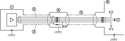
1. Readhead
2. Inner shield
3. Outer shield
4. Connector
5. Single shield extension
6. Customer electronics
7. Output signals
What is the flex life of the readhead cable?
The flex life of all readhead cable types is tested to > 20 x 106 cycles.
Depending on the diameter of the cable, the cable flex life is tested at either 20 or 50 mm bend radius. Please refer to the relevant encoder system installation guides.
What is the maximum length of extension cable without signal distortion?
Extension cable length information for specific systems is detailed in the installation guides.
Do I need to calibrate my Renishaw encoder system ?
Renishaw incremental encoder systems generate relative position signals immediately on power-up but reference marks require calibration for optimal performance. More information about these specific systems can be found in our installation guides.
What is the connector on the ATOM DX™ top exit variant?
The connector on the ATOM DX readhead is a 10 way JST and the mating connector is 10SUR-32S.
Does Renishaw offer cables for top exit readheads?
Yes, we offer cables with a 15 way D-type connector or a 10 way JST (SUR) connector in four lengths including 0.5, 1, 1.5 and 3 metres. Part number details can be found in the ATOM DX data sheet.
What is the best way to quickly and easily install Renishaw encoder readheads and scales?
Please refer to our installation guides and videos for specific encoder systems.
Additionally, our optional Advanced Diagnostic Tools can assist with challenging motion control installations, as they can help make encoder set-up and fault diagnosis quick and easy.
Technical functionality
What is an encoder and how does it work?
An encoder is an electromechanical device that converts information from one format or code into another. A position encoder, such as those made by Renishaw, converts linear or rotary motion into an electrical signal that provides information on position and direction of motion.
Position encoders can employ a range of different sensing technologies: Renishaw specialises in optical, inductive and laser encoder systems. RLS, a Renishaw associate company, specialises in magnetic encoders.
Find out more in our introduction to encoder systems article.
What is the difference between analogue and digital encoders?
Incremental encoder readheads give position information as analogue or digital signals. Digital signals can be generated within the readhead or through an external interface unit.
Analogue output (or digital from an external interface) consists of a sinusoidal signal and a cosine signal that are 90° out of phase with each other. These signals are known as analogue quadrature and can be read by a wide range of drives and controllers. A digital output can be generated by feeding an analogue output through an external interface unit. Features ony available through an external interface unit are:
- Very fine interpolation (for resolutions of 2 nm or 1 nm)
- Some interfaces have a set-up LED that displays the signal status for when the readhead is hidden or inaccessible.
Digital signal (built-in) output is created by converting analogue signals into two digital square waves. These are 90° out of phase with each other and have a much shorter period than the original analogue signals. Digital signals are also known as digital quadrature and can be read by a wide range of drives and controllers.
What is quadrature output?
Quadrature output is a form of signal that delivers incremental position movement and direction information. The word quadrature can be applied to either analogue or digital signals.
Analogue quadrature
The simplest and most universal incremental position signal is formed from a sinusoidal voltage signal, typically 1Vpp, accompanied by a corresponding cosinusoidal signal which is 90° out of phase with the first signal. This is known as analogue quadrature and can be handled by a wide range of drives and controllers.
Digital quadrature
Digital signals are formed from an analogue signal which is interpolated down to provide two digital square waves at a 90° phase difference and a much shorter signal period than the original analogue sinusoidal signal. This is known as digital quadrature and is easily read by a wide range of drives and controllers.
Why is there a difference between theoretical speed and achievable maximum speed for digital encoder systems with clocked outputs?
For clocked output systems, Renishaw quotes the clock frequency option as the recommended counting frequency of the receiving electronics. This is greater than the actual clocked output frequency of the encoder due to a safety factor being added. This safety factor allows for clock oscillator tolerances, line driver, cable and line receiver skews, cyclic error (SDE) and jitter, which all contribute to a lower minimum edge separation of the incremental signal than that calculated for a theoretically perfect system.
For example, a 20 MHz Ti TONiC™ interface option has an actual clocked output of 15 MHz, resulting in a maximum speed of 1.35 m/s for a 0.1 μm resolution encoder. Theoretical maximum speed for this system would be 1.5 m/s, although, for the reasons stated above, this would not be possible.
Analogue signal bandwidth will also restrict maximum speed to an upper limit irrespective of the clocked output of the encoder. In the case of the TONiC system, this limit is 10 m/s.
What is a ‘clocked output option' and how to choose the correct clock frequency?
The 'clocked output option' should be used when it is required to limit the maximum frequency the encoder can output. Without limiting the output frequency miscounting of the receiving electronics will occur when its maximum input frequency is exceeded. This is particularly important when the encoder is stationary (or moving very slowly) when it is possible to get rapid changes in output state. The clocked output frequency should be chosen to be equal or less than the maximum input frequency of the receiving electronics. It should be noted that choosing a clocked frequency much less than the input frequency will result in a reduction of maximum speed of the encoder.
Does Renishaw produce any incremental encoder systems that operate with a ultra-fine pitch (<4 µm) scale?
Renishaw produces incremental encoders with either 20 µm or 40 µ pitch scales. Although there are finer pitch encoder systems available, it does not necessarily follow that these systems give a better overall performance. Ultra-fine pitch (<4 µm) systems can be more difficult to set up and can have limited speed capability and poor dirt immunity. Also, by employing effective incremental signal conditioning and interpolation techniques, many Renishaw encoder systems give comparable resolution, accuracy and cyclic error (Sub-Divisional Error) to finer pitch systems.
For example, the VIONiC™ optical incremental encoder series integrates Renishaw's market-proven filtering optics and advanced interpolation technology to provide ultra low Sub-Divisional Error (SDE), excellent dirt immunity and high operating speeds.
For applications requiring absolute feedback, the high-speed, ultra-low jitter and fine resolution offered by the RESOLUTE™ encoder enable high throughput with low error rates. Manufacturing requiring precision measurement can be achieved using these encoders on linear, rotary or partial arc (angle) axes.
Discover the testing done by Renishaw and ACS that demonstrated how advanced servo-control algorithms can be used to achieve effective jitter equivalent to that for ultra-fine pitch products
How to choose between an absolute or incremental encoder for an application?
Absolute and incremental encoders are suitable for a wide range of position measurement and motion control applications. They offer slightly different behaviour and performance.
Absolute encoder systems report and retain complete position information at all times including through power cycles. They immediately acquire position without any motion being required. They are widely used in surgical robots and machines where homing cycles to a fixed reference mark are not desirable.
Incremental encoder systems report movement relative to their previous position - the output position signal increments or decrements (depending on direction) position by one count at a time as the readhead moves relative to the scale. A fixed datum location is generally required from a known reference position feature. This datum position is lost when power is cut. They are widely used in factory automation, co-ordinate measuring machines (CMMs) and semiconductor manufacturing.
What is the position (time) delay of incremental encoder signals?
The time delay through an incremental encoder system depends on many factors, including the output type, optical stage, analogue and digital electronics stages, line driver/receiver and cabling design/length. These figures are known but difficult to document. Therefore, for exact application advice, please contact your nearest Renishaw representative.
Which serial interfaces do Renishaw absolute encoders support?
Renishaw absolute encoders are supported by the following serial interfaces, also known as protocols:
| Optical encoder series | Serial interfaces |
| RESOLUTE™ open | BiSS® C BiSS Safety FANUC Mitsubishi Panasonic Siemens DRIVE-CLiQ® Yaskawa |
| EVOLUTE™ open | BiSS® C FANUC Mitsubishi Panasonic Siemens DRIVE-CLiQ® Yaskawa |
| FORTiS-S™ enclosed | BiSS® C BiSS Safety FANUC Mitsubishi Panasonic Siemens DRIVE-CLiQ® Yaskawa |
| FORTiS-N™ enclosed | BiSS® C BiSS Safety FANUC Mitsubishi Panasonic Siemens DRIVE-CLiQ® Yaskawa |
What is the difference between accuracy, resolution and repeatability?
These 3 terms can be confused with each other. Their definitions are as follows, as per our glossary:
- Accuracy: how close to the real value a measured position is.
- Resolution: the smallest measurement step output by an encoder: this is the minimum distance that the encoder must move to change its output by one count.
- Repeatability: the ability of the encoder to report the same position each time it arrives at a certain point along the axis.
What is the difference between jitter and Sub-Divisional Error (SDE )?
These 2 terms are often confused with each other. Their definitions are as follows:
- Jitter: the amount of positional noise output by an encoder when it is not moving. This figure is normally quoted in RMS, but there are many ways to measure positional noise; the bandwidth of the measurement is particularly crucial. Encoders with lower jitter can hold position better and generate less heat in linear motors. They will also exhibit smoother velocity control at low speeds.
- Sub-Divisional Error: The measurement error within one signal period. This error mechanism is due to imperfections in the shape or centring of the encoder output signal Lissajous. SDE can cause velocity ripple problems on linear motor or DDR motor axes. High SDE can cause an axis to make an audible noise, and heat can be generated. In machine tool applications, high SDE can cause poor surface finish and on scanning machines it can cause blurred images.
Compliance
Are Renishaw optical encoders and scales RoHS compliant?
Yes, please refer to our compliance certificates webpage.
Are Renishaw optical encoders and scales using minerals from conflict areas ?
Please refer to our compliance certificates webpage.
Do Renishaw optical encoders and scales comply with EU legislation (CE declarations of conformity)?
Yes, please refer to our compliance certificates webpage.
Applications
Are Renishaw readhead cables suitable for use in robotic applications that require the cable to be flexed?
If the readhead cable minimum bend radius is not exceeded (see relevant data sheets) then the cable will have a minimum flex life of 20 000 000 operations. However the cable is not designed for applications that rotate (twist) the cable along its length. It is not recommended to bend or flex UHV readhead cables as this will damage the cable.
Which encoder is recommended for high volume OEM applications where machine build time is critical?
The EVOLUTE™ absolute linear encoder series provides fine-resolution true-absolute position measurement with generous installation tolerances and robust dirt immunity for versatile metrology performance.
Similarly the QUANTiC™ incremental encoder series has been designed for manufacturers and system integrators with excellent metrology and exceptionally wide installation tolerances from a super-compact readhead form factor.
Both systems are well suited to high volume OEM applications where machine build time is critical as time saved in component installation allows shorter manufacturing lead times and ultimately higher profitability.
Please refer to our glossary for the definitions of the technical terminology used on this page.
Contact our sales team today
Get in contact with your local office to find out more information and speak to an expert.