How Renishaw optical encoders work
Optical encoders are known for their high accuracy and reliability, making them essential in many industrial and scientific applications. Renishaw provides a range of enclosed and open, incremental and absolute, optical encoders that can measure linear, partial arc and rotary motion.
Explore the design advantages of Renishaw optical encoders
FORTiS
The FORTiS enclosed optical encoder houses the encoder's electronics and optics within a sealed unit that is attached to a readhead body. Both the sealed optical unit and the encoder's scale are further protected within a sealed enclosure. This design provides high resistance to the ingress of liquids and solid debris contaminants.
The enclosed linear encoder features an extruded enclosure with longitudinally attached interlocking lip seals and sealed end caps. The readhead body is joined to a sealed optical unit by a blade, which travels through the lip seals along the length of the encoder.
RESOLUTE
The RESOLUTE encoder communicates bi-directionally in purely serial format, using a variety of industry-standard protocols, of both proprietary and open standard.
The process begins...
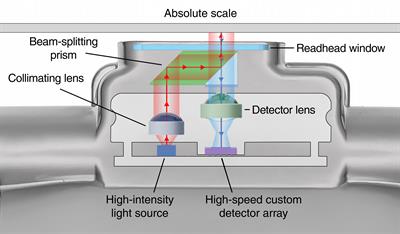
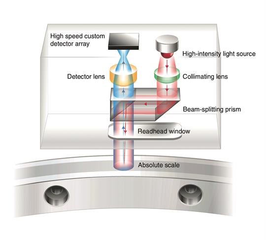
The controller initiates operation by sending a demand message to the readhead, instructing it to capture the absolute position on the linear or rotary scale at that instant. The head responds by flashing a high-power LED source to illuminate the scale. The flash duration is as brief as 100 ns to minimise image blur on moving axes. Crucially its timing is controlled within a few nanoseconds to preserve the relationship between demanded and reported position, one of the essential features that makes RESOLUTE ideally suited to very high specification motion systems.
Single track scale
The scale is essentially a single track of full-width contrasting lines, based on a nominal period of 30 µm. The absence of multiple parallel tracks gives important immunity from yaw errors and much more lateral tolerance in head position.
Image acquisition
The scale is imaged, via an aspheric lens which minimises distortion, onto a custom detector array designed specifically for RESOLUTE. The optical arrangement, with a folded illumination path but direct imaging, is highly compact yet stable thus assuring the fidelity essential for excellent metrology.
Data decoding and analysis
Once captured by the detector, the image is transferred via an analogue-to-digital converter (ADC) to a powerful Digital Signal Processor (DSP). Specially developed algorithms then obtain a true absolute, but relatively coarse position from the code embedded in the scale. This process is checked, and corrections are made by further algorithms in the DSP which exploit redundancy and intentional restrictions in the scale code. Meanwhile other routines calculate a very high resolution fine position, which is then combined with the coarse position to provide a truly absolute and very high resolution location.
Final checks and data output
After final error checking procedures this information is uploaded in the appropriate protocol to the controller as a pure serial word representing position to within 1 nm. Protection against electrical noise disturbance is provided by addition of a Cyclic Redundancy Check (CRC). The entire process can take as little as a few microseconds and be repeated up to 25 000 times per second. By a variety of techniques, including adjusting the light flash duration to the axis speed, this performance is achieved at up to 100 m/s while, crucially, preserving exceptionally low positional jitter at lower operating speeds.
And the result is...
An encoder with generous installation tolerances: RESOLUTE allows ±0.5° in yaw, pitch and roll and an impressive ±150 µm in rideheight. Meanwhile the generous optical footprint and advanced error correcting procedures confer excellent immunity to optical contamination, both particulate and greasy smears. All this while maintaining 1 nm resolution at 100 m/s: RESOLUTE is the answer to the toughest absolute challenge.
EVOLUTE
The EVOLUTE encoder communicates bi-directionally in purely serial format, using a variety of industry-standard protocols, of both proprietary and open standard.
The process begins...
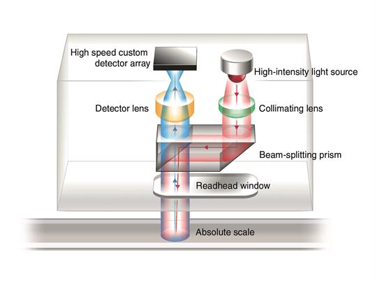
The controller initiates operation by sending a demand message to the readhead, instructing it to capture the absolute position on the linear scale at that instant. The head responds by flashing a high-power LED source to illuminate the scale. The flash duration is as brief as 100 ns to minimise image blur on moving axes. Crucially its timing is controlled within a few nanoseconds to preserve the relationship between demanded and reported position, making the EVOLUTE series ideally suited for high specification motion systems.
Single track scale
The scale is essentially a single track of full-width contrasting lines, based on a nominal period of 50 µm. The absence of multiple parallel tracks gives important immunity from yaw errors and a higher lateral tolerance in head position.
Image acquisition
The scale is imaged, via an aspheric lens which minimises distortion, onto a custom detector array. The optical arrangement, with a folded illumination path but direct imaging, is highly compact yet stable thus assuring the fidelity essential for excellent metrology.
Data decoding and analysis
Once captured by the detector, the image is transferred via an analogue-to-digital converter to a powerful Digital Signal Processor (DSP). Specially developed algorithms then obtain a true absolute, but relatively coarse position from the code embedded in the scale. This process is checked, and corrections are made by further algorithms in the DSP which exploit redundancy and intentional restrictions in the scale code. Meanwhile other routines calculate a very high resolution fine position, which is then combined with the coarse position to provide a truly absolute and very high resolution location.
Final checks and data output
After final error checking procedures, position information is uploaded in the appropriate protocol to the controller as a pure serial word. Protection against electrical noise disturbance is provided by addition of a Cyclic Redundancy Check (CRC). The entire process can take as little as a few microseconds and be repeated up to 25 000 times per second. By a variety of techniques, including adjusting the light flash duration to the axis speed, this performance can be achieved at up to 100 m/s while preserving exceptionally low positional jitter at lower operating speeds.
And the result is...
The EVOLUTE encoder offers generous installation tolerances of ±0.75° in yaw, and ±0.5° in pitch and roll, along with an impressive ±250 µm in rideheight. Meanwhile the generous optical footprint and advanced error correction procedures provide excellent immunity to optical contamination, including both particulate and greasy smears, while maintaining 50 nm resolution of up to 100 m/s.
QUANTiC
QUANTiC encoders feature the third generation of Renishaw's unique filtering optics that average the contributions from many scale periods and effectively filter out non-periodic features such as dirt. The nominally square-wave scale pattern is also filtered to leave a pure sinusoidal fringe field at the detector. Here, a multiple finger structure is employed, fine enough to produce photocurrents in the form of four symmetrically phased signals. These are combined to remove DC components and produce sine and cosine signal outputs with high spectral purity and low offset whilst maintaining bandwidth to beyond 500 kHz.
Fully integrated advanced dynamic signal conditioning, including Auto Gain, Auto Balance and Auto Offset Controls, ensures low Sub-Divisional Error (SDE) of typically < ±80 nm for small rotary systems, typically < ±150 nm for large rotary systems and < ±80 nm for linear systems.
This evolution of filtering optics, combined with carefully designed electronics, provide incremental signals with wide bandwidth achieving a maximum speed of 8 800 rpm for rotary systems, 24 m/s for linear systems, with the lowest positional jitter (noise) of any encoder in its class. Interpolation is within the readhead, with fine resolution versions being further augmented by additional noise-reducing electronics to achieve jitter down to 2.73 nm RMS.
The IN-TRAC reference mark is fully-integrated in the incremental scale and is detected by a photodetector within the readhead. This unique arrangement also benefits from an automatic calibration routine that electronically phases the reference mark and optimises the incremental signals.
TONiC
The TONiC encoder series features the third generation of Renishaw's unique filtering optics that average the contributions from many scale periods and effectively filter out non-periodic features such as dirt. The nominally square-wave scale pattern is also filtered to leave a pure sinusoidal fringe field at the detector. Here, a multiple finger structure is employed, fine enough to produce photocurrents in the form of four symmetrically phased signals. These are combined to remove DC components and produce sine and cosine signal outputs with high spectral purity and low offset while maintaining bandwidth to beyond 500 kHz.
Fully integrated advanced dynamic signal conditioning, Auto Gain , Auto Balance and Auto Offset Controls combine to ensure ultra-low Sub- Divisional Error (SDE) of typically < ±30 nm.
This evolution of filtering optics, combined with carefully-selected electronics, provide incremental signals with wide bandwidth achieving a maximum speed of 10 m/s with the lowest positional jitter (noise) of any encoder in its class. Interpolation is by CORDIC algorithm within the TONiC Ti interface, with fine resolution versions being further augmented by additional noise-reducing electronics to achieve jitter of just 0.5 nm RMS.
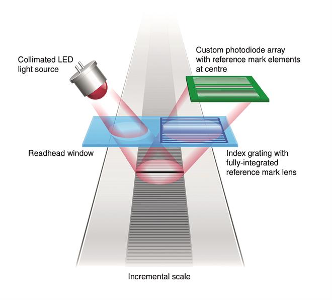
The IN-TRAC reference mark is fully-integrated in the incremental scale and is detected by a split photodetector within the readhead. As the diagram shows, the reference mark split detector is embedded directly into the centre of the incremental channel linear photodiode array ensuring greater immunity from yaw-dephasing. Yielding a reference mark output that is bi-directionally repeatable to unit of resolution at all speeds. This unique arrangement also benefits from an automatic calibration routine that electronically phases the reference mark and optimises the dynamic signal conditioning
VIONiC
The VIONiC encoder features the third generation of Renishaw's unique filtering optics that average the contributions from many scale periods and effectively filter out non-periodic features such as dirt. The nominally square-wave scale pattern is also filtered to leave a pure sinusoidal fringe field at the detector. Here, a multiple finger structure is employed, fine enough to produce photocurrents in the form of four symmetrically phased signals. These are combined to remove DC components and produce sine and cosine signal outputs with high spectral purity and low offset while maintaining bandwidth to beyond 500 kHz.
Fully integrated advanced dynamic signal conditioning, Auto Gain , Auto Balance and Auto Offset Controls combine to ensure ultra-low Sub-Divisional Error (SDE) of typically < ±15 nm.
This evolution of filtering optics, combined with carefully-selected electronics, provide incremental signals with wide bandwidth achieving a maximum speed of 12 m/s with the lowest positional jitter (noise) of any encoder in its class. Interpolation is within the readhead, with fine resolution versions being further augmented by additional noise-reducing electronics to achieve jitter of just 1.6 nm RMS.
The IN-TRAC™ reference mark is fully-integrated in the incremental scale and is detected by a split photodetector within the readhead. As the diagram shows, the reference mark split detector is embedded directly into the centre of the incremental channel linear photodiode array ensuring greater immunity from yaw-dephasing. This unique arrangement also benefits from an automatic calibration routine that electronically phases the reference mark and optimises the incremental signals.
ATOM DX
The ATOM DX encoder employs the market proven filtering optics used in Renishaw incremental encoders such as TONiC and VIONiC. ATOM DX readheads feature a non-collimated LED light source located centrally between the incremental and reference mark sensors: this high divergence LED produces a low profile height with a footprint at the scale that is much larger than the LED, enabling illumination of incremental and reference mark regions. The incoherent LED produces a signal of high harmonic purity allowing high resolution interpolation. Efficient photometry also produces an output signal with low jitter. A significant benefit of this filtering optics scheme is that ATOM DX does not generate measurement errors due to scale undulation or contamination.
Fully integrated advanced dynamic signal conditioning methods, including Auto Gain Control, Auto Balance Control and Auto Offset Control, combine to ensure ultra-low Sub-Divisional Error (SDE) of typically < ±15 nm.
The combination of filtering optics and carefully-selected electronics generates incremental position feedback signals with wide bandwidth achieving a maximum speed of 12 m/s with the lowest positional jitter (noise) of any encoder in its class. Digital signal interpolation is generated within the readhead, with fine resolution versions being further augmented by additional noise-reducing electronics to achieve jitter of just 1.6 nm RMS.
The ATOM DX encoder series uses a large, single feature, off-track optical reference mark for good contamination immunity. Phasing of the reference mark is achieved with a simple, intuitive auto-calibration routine, as used in the QUANTiC™ and VIONiC™ encoder series.
ATOM
The ATOM encoder series uses a non-collimated LED located centrally between the incremental and reference mark sensors. This high divergence LED produces a low profile height with a footprint at the scale that is much larger than the LED, enabling illumination of incremental and reference mark regions.
This encoder employs the same filtering optics scheme as used in all Renishaw's incremental encoders. The incoherent LED produces a signal of high harmonic purity allowing high resolution interpolation. Efficient photometry also produces a low jitter signal. A further benefit of the filtering optics scheme is that ATOM does not generate measurement errors due to scale contamination and undulations.
The ATOM encoder uses a large single feature off-track optical reference mark for good contamination immunity. Phasing of the reference mark is as simple an operation as with TONiC.
Discover our range of open and enclosed optical, inductive, laser and magnetic encoders designed to meet your industrial automation needs.
Contact our sales team today
Get in contact with your local office to find out more information and speak to an expert.