Navigation
Datuming SCR600
Software alignment for the SCR600
This section describes the suggested software alignment routine to find the positions of the SCR600 ports. These instructions assume that the SCR600 has the X-axis as its docking axis.
Port lids 1 and 4 should be in the retained position, which is achieved by sliding the lids back to the extreme of their travel where a magnet / slot mechanism will hold the lids open.
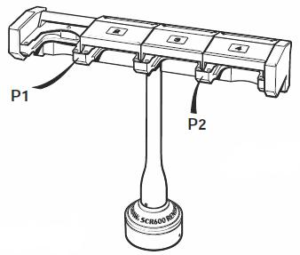
Step 1 - Establishing docking depth (X)
- Take points P1 and P2 as shown below.
- To establish the docking depth (X-axis) for all ports, the following calculation should be used:
X position of P1 / P2 + stylus ball radius + 21.5 mm (0.85 in)
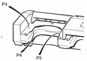
Step 2 - Establishing docking height (Z)
- Take point P3 as shown below.
- To establish the docking height (Z-axis) for all ports, the following calculation should be used:
Z position of P3 - stylus ball radius - stylus length - 8.4 mm (0.33 in)
Step 3 - Establishing docking centre for port 1 (Y1)
- Take points P4 and P5 as shown below.
- Calculate the centre line of these points.
Step 4 - Establishing docking centre for ports 2 to 4
- Using the centre of port 1 as a reference, add 53.5 mm (2.11 in) to establish the docking centre for port 2 (Y2)
- Using the centre of port 2 as a reference, add 53.5 mm (2.11 in) to establish the docking centre for port 3 (Y3)
- Using the centre of port 3 as a reference, add 53.5 mm (2.11 in) to establish the docking centre for port 4 (Y4)
Position of docking target co-ordinates
Port 1 = X, Y1, Z
Port 2 = X, Y2, Z
Port 3 = X, Y3, Z
Port 4 = X, Y4, Z